Applications information – Rainbow Electronics MAX5097 User Manual
Page 13
lower end of the AM band. The MAX5096 is suitable for
noise-sensitive applications like AM radio power sup-
ply. For an application where size is more important,
use the MAX5097, which runs at 330kHz frequency.
The high-frequency operation reduces the size and
cost of the external inductor and capacitor. The
MAX5096/MAX5097 can be synchronized using an
external signal. The MAX5096 can be synchronized
from 120kHz to 500kHz, while the MAX5097 is capable
of synchronizing from 300kHz to 500kHz. The external
synchronization feature makes frequency hopping pos-
sible depending on the selected AM channel. Connect
SYNC to ground, if not used.
Thermal Protection
When the junction temperature exceeds T
J
= +165°C,
an internal thermal sensor signals the shutdown logic,
which turns off the regulator (both in Buck Mode and
LDO Mode), and discharges the soft-start capacitor
allowing the IC to cool. The thermal sensor turns the
regulator on again after the IC’s junction temperature
cools by 20°C, resulting in a cycled output during con-
tinuous thermal-overload conditions. The thermal hys-
teresis and a soft-start period limit the average power
dissipation into the device during continuous fault con-
dition. During operation, do not exceed the absolute
maximum junction temperature rating of T
J
= +150°C.
Applications Information
Output Voltage Selection
The MAX5096/MAX5097 can be configured as either a
preset fixed output voltage or an adjustable output volt-
age device. Connect ADJ to ground to select the facto-
ry-preset output voltage option (Figure 2). The
MAX5096A/MAX5097A and MAX5096B/MAX5097B
provide a fixed output voltage equal to 3.3V and 5V,
respectively (see the Selector Guide). The MAX5096/
MAX5097 become an adjustable version as soon as the
devices detect about 125mV at the ADJ pin. The resis-
tor-divider at ADJ increases the ADJ voltage above
125mV and also adjusts the output voltage depending
upon the resistor values. In adjustable mode, select an
output between +1.273V and +11V using two external
resistors connected as a voltage-divider to ADJ (Figure
4). Set the output voltage using the following equation:
where V
ADJ
= 1.273V and R2 is chosen to be approxi-
mately 100k
Ω.
Connect ADJ to GND if adjustable mode is not used.
Inductor Selection
Three key inductor parameters must be specified for
proper operation with the MAX5096/MAX5097: induc-
tance value (L), peak inductor current (I
PEAK
), and
inductor saturation current (I
SAT
). The minimum
required inductance is a function of operating frequen-
cy, input-to-output voltage differential, and the peak-to-
peak inductor current (
∆I
P-P
). Higher
∆I
P-P
allows for a
lower inductor value, while a lower
∆I
P-P
requires a
higher inductor value. A lower inductor value minimizes
size and cost and improves large-signal and transient
response, but reduces efficiency due to higher peak
currents and higher peak-to-peak output voltage ripple
for the same output capacitor. On the other hand, high-
er inductance increases efficiency by reducing the rip-
ple current. Resistive losses due to extra wire turns can
exceed the benefit gained from lower ripple current lev-
els, especially when the inductance is increased while
keeping the dimension of the inductor constant. A good
compromise is to choose
∆I
P-P
equal to 40% of the full
load current. Calculate the inductor value using the fol-
lowing equation:
L
V
V
V
V
f
I
OUT
IN
OUT
IN
SW
P P
=
−
Ч
Ч
−
(
)
∆
V
V
R
R
OUT
ADJ
=
×
+
1
1
2
MAX5096/MAX5097
40V, 600mA Buck Converters with Low-
Quiescent-Current Linear Regulator Mode
______________________________________________________________________________________
13
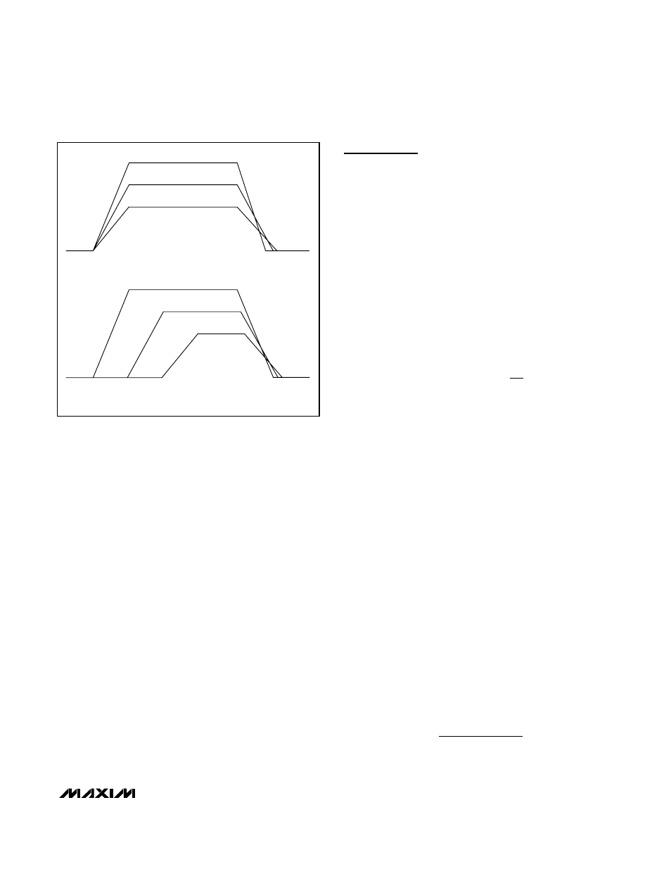
V
OUT3
V
OUT2
V
OUT1
SOFT-START
STOP
RATIOMETRIC TRACKING OUTPUTS
SEQUENCED OUTPUTS
STOP
SOFT-START
V
OUT3
V
OUT2
V
OUT1
Figure 3. Output Voltage Tracking/Sequencing