Pin description pin configuration – Rainbow Electronics MAX98500 User Manual
Page 9
_______________________________________________________________________________________ 9
MAX98500
Boosted 2.2W Class D Amplifier
with Automatic Level Control
Pin Description
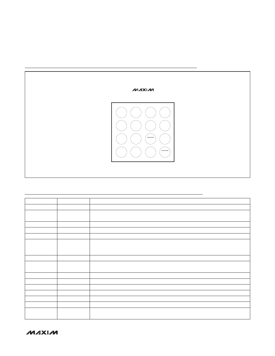
Pin Configuration
MAX98500
V
CCOUT
LX
BSTPGND
PVDD
2
3
4
1
A
GAIN
RKNEE
V
BAT
SPKP
B
SPKPGND
TOP VIEW
(BUMP SIDE DOWN)
WLP
AGND
SPKN
C
INP
INN
SPKPGND
D
+
SDBST
SDSPK
BUMP
NAME
FUNCTION
A1
PVDD
Speaker Amplifier Power Supply. Bypass to SPKPGND with a 0.1
mF capacitor.
A2
V
CCOUT
Boost Converter Output. Connect a 22
mF (0805) capacitor between V
CCOUT
and
BSTPGND.
A3
LX
Boost Switch Input
A4
BSTPGND
Boost Power Ground
B1
SPKP
Positive Speaker Output
B2
GAIN
Gain Select Input. Connect GAIN to ground to set the speaker gain to 6dB. Leave GAIN
unconnected to set the speaker gain to 15.5dB. Connect GAIN to V
BAT
to set the speaker
gain to 20dB.
B3
RKNEE
ALC Knee Voltage Set Input. Set the ALC knee voltage with a resistor to AGND.
B4
V
BAT
Battery Voltage Input. Connect a 10
mF (0805) capacitor between V
BAT
and BSTPGND.
Include at least 22
mF of system bulk capacitance.
C1
SPKN
Negative Speaker Output
C2, D1
SPKPGND
Speaker Ground
C3
SDSPK
Speaker Output Shutdown. Drive SDSPK low to shutdown the speaker output.
C4
AGND
Analog Ground
D2
INP
Positive Audio Input
D3
INN
Negative Audio Input
D4
SDBST
Boost Converter Shutdown. Drive SDBST low to shutdown the boost converter and the
speaker output.