Applications information, Table 2. shutdown configurations – Rainbow Electronics MAX98500 User Manual
Page 11
______________________________________________________________________________________ 11
MAX98500
Boosted 2.2W Class D Amplifier
with Automatic Level Control
Shutdown
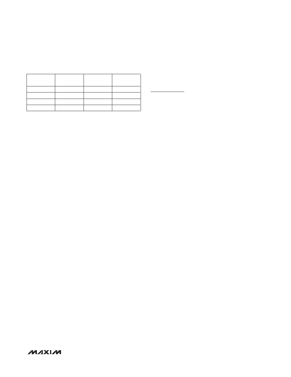
The MAX98500 features two active-low shutdown inputs
(SDSPK and SDBST). Table 2 shows the different shut-
down configurations.
Click-and-Pop Suppression
The MAX98500 speaker amplifier features Maxim’s com-
prehensive click-and-pop suppression. During startup,
the click-and-pop suppression circuitry reduces any
audible transient sources internal to the device. When
entering shutdown, the differential speaker outputs ramp
down to SPKPGND quickly and simultaneously.
Current-Limit and Thermal Protection
The IC features overcurrent and thermal protection.
The IC shuts down when the V
CCOUT
output decreases
to about 80% of the expected output. The IC also
enters into shutdown when the die temperature exceeds
+165NC. The device remains in shutdown until power
is reset or SDBST is toggled low and back high after
the fault condition has been removed. The IC speaker
amplifier also features a 2A (typ) short-circuit protection
scheme.
Boost Converter
Soft-Start
The MAX98500 features a two-stage, soft-start, power-
up sequence. When SDBST is taken high and V
BAT
is
above UVLO the soft-start first ramps V
CCOUT
quickly
to V
BAT
voltage with a battery current of 300mA (typ).
Once the V
CCOUT
reaches the V
BAT
voltage, the internal
switching turns on and ramps the V
CCOUT
to 5.5V in 5ms
(typ), see the Soft-Start graph in the Typical Operating
Characteristics. The maximum load current is available
after the soft-start is completed.
Undervoltage Lockout (UVLO)
The undervoltage lockout (UVLO) circuit compares the
voltage at V
BAT
with the UVLO threshold (2.2V typ) to
ensure that the input voltage is high enough for reliable
operation. Once the V
BAT
voltage exceeds the UVLO
threshold, the soft-start begins. When the input voltage
falls below the UVLO threshold, the boost converter and
speaker amplifier turn off.
Applications Information
Filterless Class D Operation
Traditional Class D amplifiers require an output filter to
recover the audio signal from the amplifier’s output. The
filter adds cost, increases the solution size of the ampli-
fier, and can decrease efficiency and THD+N perfor-
mance. The traditional PWM scheme uses large differen-
tial output swings (2 x supply voltage peak-to-peak) and
causes large ripple currents. Any parasitic resistance in
the filter components results in a loss of power and low-
ers the efficiency.
The MAX98500 does not require an output filter. The
device relies on the inherent inductance of the speaker
coil and the natural filtering of both the speaker and
the human ear to recover the audio component of the
square-wave output. Eliminating the output filter results
in a smaller, less costly, and more efficient solution.
Because the frequency of the MAX98500 output is well
beyond the bandwidth of most speakers, voice coil
movement due to the square-wave frequency is very
small. Although this movement is small, a speaker not
designed to handle the additional power can be dam-
aged. For optimum results, use a speaker with a series
inductance > 10FH. Typical 8I speakers exhibit series
inductances in the 20FH to 100FH range.
RF Susceptibility
GSM radios transmit using time-division multiple access
(TDMA) with 217Hz intervals. The result is an RF signal
with strong amplitude modulation at 217Hz and its har-
monics that is easily demodulated by audio amplifiers.
The MAX98500 is designed specifically to reject RF
signals; however, PCB layout has a large impact on the
susceptibility of the end product.
In RF applications, improvements to both layout and
component selection decrease the MAX98500’s suscep-
tibility to RF noise and prevent RF signals from being
demodulated into audible noise. Trace lengths should be
kept below 1/4 of the wavelength of the RF frequency of
interest. Minimizing the trace lengths prevents them from
functioning as antennas and coupling RF signals into the
MAX98500. The wavelength (
l) in meters is given by:
l = c/f where c = 3 x 10
8
m/s, and f = the RF frequency
of interest.
Table 2. Shutdown Configurations
SDBST
SDSPK
BOOST
STATUS
SPEAKER
STATUS
Low
Low
Off
Off
Low
High
Off
Off
High
Low
On
Off
High
High
On
On