Rainbow Electronics MAX6652 User Manual
Page 7
MAX6652
Temperature Sensor and System Monitor
in a 10-Pin µMAX
_______________________________________________________________________________________
7
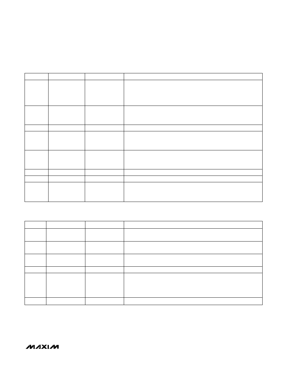
Table 5. Interrupt Status Register (Address 41h, Power-Up Default = 00h)
Table 4. Configuration Register (Address 41h, Power-Up Default = 00h)
BIT
NAME
READ/WRITE
DESCRIPTION
0
Start/Stop
R/W
This bit controls the monitoring loop. Setting the bit to 0 stops the
monitoring loop and puts the device into shutdown mode. The I
2
C/SMBus
interface is still active during the shutdown mode. Setting the bit to 1 starts
the monitoring cycle. All high/low limits should be set before setting this
bit to 1.
1
Interrupt Enable
R/W
This bit is used to enable or disable the interrupt output. Setting the bit to
1 enabes the interrupt output; setting the bit to 0 disables the interrupt
output.
2
Reserved
—
—
3
Interrupt Clear
R/W
This bit is used to clear the interrupt output when it is set to high. It will not
affect the interrupt status register. The monitoring loop will not start until
the bit is set to 0.
4
Line Frequency
Select
R/W
This bit controls the internal clock frequency. Setting the bit to 1 changes
the clock frequency to 51.2kHz from 61.4kHz. This can improve the
measurement accuracy when the power-line frequency is at 50Hz.
5
Short Cycle
R/W
This bit reduces the conversion rate by a factor of four when it is set to 1.
6
Reserved
—
—
7
Reset
R/W
This bit is used as a reset signal for the register initialization. The 1 of this
bit will reset all the register values into the power-up default mode,
including bit 7 itself.
BIT
NAME
READ/WRITE
DESCRIPTION
0
2.5V
IN
Error
R
A 1 indicates either a high or low limit has been exceeded at the 2.5V
IN
input.
1
12V
IN
Error
R
A 1 indicates either a high or low limit has been exceeded at the 12V
IN
input.
2
3.3V
IN
Error
R
A 1 indicates either a high or low limit has been exceeded at the 3.3V
IN
input.
3
V
CC
Error
R
A 1 indicates either a high or low limit has been exceeded at the V
CC
input.
4
Temperature Error
R
A 1 indicates either a high or low limit has been exceeded at the internal
temperature sensor. The conditions that will generate and clear this bit
depend on the temperature interrupt mode selected by bits 0 and 1 in the
temperature configuration register.
5, 6, 7
Reserved
—
—