Typical application circuit, Functional diagram – Rainbow Electronics MAX6652 User Manual
Page 12
Maxim cannot assume responsibility for use of any circuitry other than circuitry entirely embodied in a Maxim product. No circuit patent licenses are
implied. Maxim reserves the right to change the circuitry and specifications without notice at any time.
12 ____________________Maxim Integrated Products, 120 San Gabriel Drive, Sunnyvale, CA 94086 408-737-7600
© 2001 Maxim Integrated Products
Printed USA
is a registered trademark of Maxim Integrated Products.
MAX6652
Temperature Sensor and System Monitor
in a 10-Pin µMAX
Typical Application Circuit
0.1
µF
V
CC
V
CC
10k
Ω
SCL
SDA
ADD
GND
3.3V
IN
12V
IN
2.5V
IN
TO 3.3V
3.3V
TO 12V
TO 2.5V
N.C.
ALERT
CPU
MAX6652
I
2
C/SMBus
CONTROLLER
V
CC
SCL
SDA
ADD
3.3V
IN
12V
IN
2.5V
IN
ALERT
ADC
VOLTAGE
REFERENCE
DATA AND
CONTROL
LOGIC
TEMPERATURE
SENSOR
INPUT VOLTAGE
SCALING AND
MULTIPLEXER
I
2
C/SMBus-
COMPATIBLE
INTERFACE
MAX6652
Functional Diagram
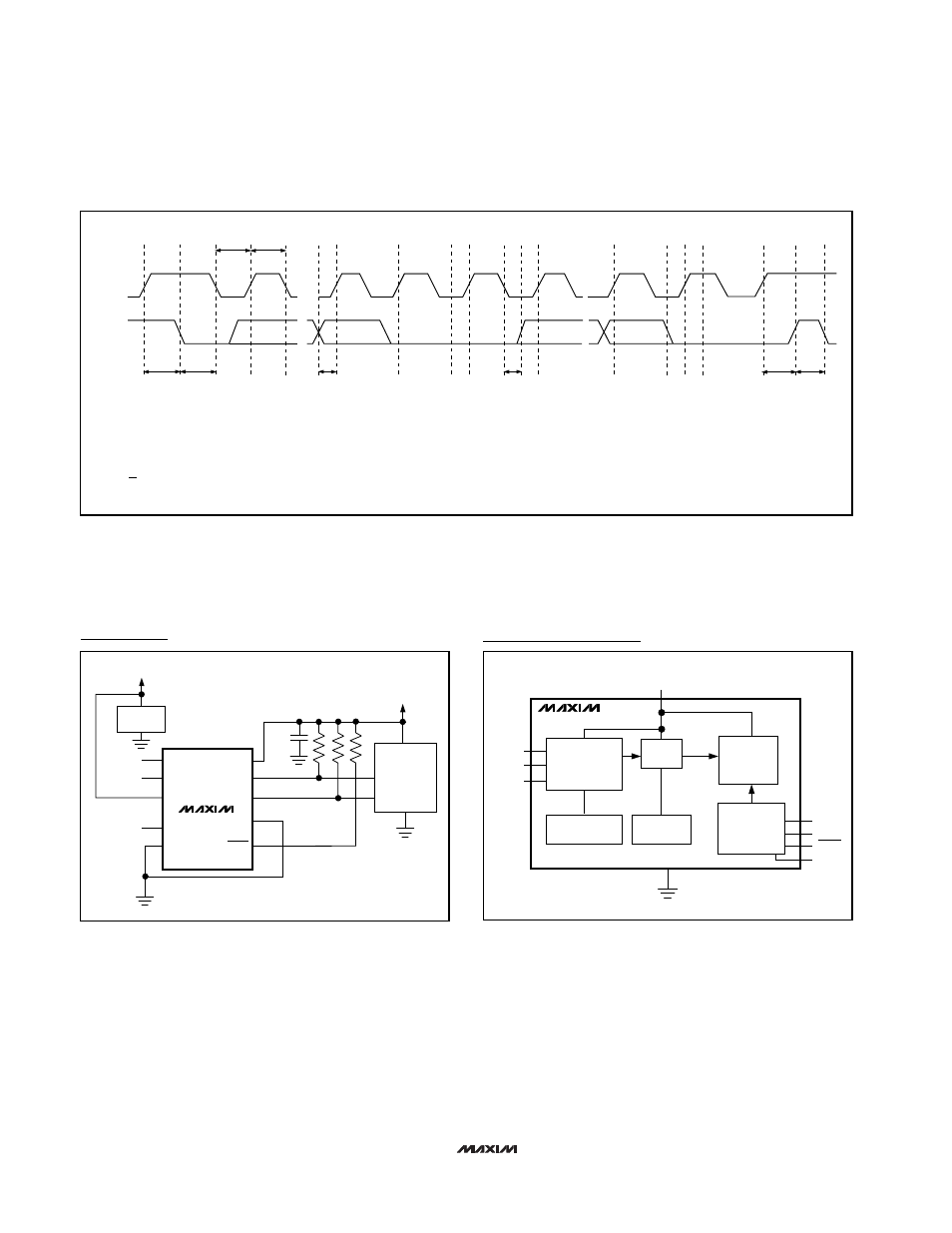
Figure 4. I
2
C/SMBus Read Timing Diagram
SMBCLK
A
B
C
D
E
F
G
H
I
J
K
SMBDATA
t
SU:STA
t
HD:STA
t
LOW
t
HIGH
t
SU:DAT
t
HD:DAT
t
SU:STO
t
BUF
L
M
F = ACKNOWLEDGE BIT CLOCKED INTO MASTER
G = MSB OF DATA CLOCKED INTO MASTER
H = LSB OF DATA CLOCKED INTO MASTER
I = MASTER PULLS DATA LINE LOW
J = ACKNOWLEDGE CLOCKED INTO SLAVE
K = ACKNOWLEDGE CLOCK PULSE
L = STOP CONDITION
M = NEW START CONDITION
A = START CONDITION
B = MSB OF ADDRESS CLOCKED INTO SLAVE
C = LSB OF ADDRESS CLOCKED INTO SLAVE
D = R/W BIT CLOCKED INTO SLAVE
E = SLAVE PULLS SMBDATA LINE LOW