Applications information, Chip information, Table 7. temperature configuration register – Rainbow Electronics MAX6652 User Manual
Page 10
MAX6652
Temperature Sensor and System Monitor
in a 10-Pin µMAX
10
______________________________________________________________________________________
Bit 6 is reserved.Bit 7 resets all register values to their
power-up default values. To reset all registers, set bit 7
to 1. This will also reset bit 7 to its power-up value of 0.
Applications Information
Sensing Circuit Board and Component
Temperatures
Temperature sensor ICs like the MAX6652 that sense
their own die temperatures must be mounted on or
close to the object whose temperature they are intend-
ed to measure. Because there is a good thermal path
between the 10-pin µMAX package’s metal leads and
the IC die, the MAX6652 can accurately measure the
temperature of the circuit board to which it is soldered.
If the sensor is intended to measure the temperature of
a heat-generating component on the circuit board, it
should be mounted as close as possible to that compo-
nent and should share supply and ground traces (if
they are not noisy) with that component where possible.
This will maximize the heat transfer from the component
to the sensor.
The thermal path between the plastic package and the
die is not as good as the path through the leads, so the
MAX6652, like all temperature sensors in plastic pack-
ages, will be less sensitive to the temperature of the
surrounding air than to the temperature of the leads.
As with any IC, the wiring and circuits must be kept
insulated and dry to avoid leakage and corrosion,
especially if the part will be operated at cold tempera-
tures where condensation can occur.
Chip Information
TRANSISTOR COUNT: 13,446
PROCESS: BiCMOS
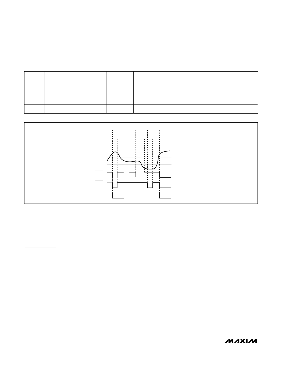
INTERRUPT
STATUS READ
T
HOT
T
HYST
TEMPERATURE
MONITORING CYCLE
DEFAULT MODE
ONE-TIME
INTERRUPT MODE
COMPARATOR MODE
ALERT
ALERT
ALERT
Figure 1. Alert Response to Temperature Interrupts
Table 7. Temperature Configuration Register
BIT
NAME
R/W
DESCRIPTION
0-1
Hot Temperature Interrupt
Mode Select
R/W
Bit 1, Bit 0
00: Default Mode
Bit 1, Bit 0
01: One-Time Interrupt Mode
Bit 1, Bit 0
10: Comparator Mode
Bit 1, Bit 0
11: Default Mode
2-7
Reserved
R/W
—