Detailed description, Applications information, Typical operating circuit – Rainbow Electronics MAX9634 User Manual
Page 6
MAX9634
1µA, 4-Bump UCSP/SOT23,
Precision Current-Sense Amplifier
6
_______________________________________________________________________________________
Detailed Description
The MAX9634 unidirectional high-side, current-sense
amplifier features a 1.6V to 28V input common-mode
range. This feature allows the monitoring of current out
of a battery with a voltage as low as 1.6V. The
MAX9634 monitors current through a current-sense
resistor and amplifies the voltage across that resistor.
The MAX9634 is a unidirectional current-sense amplifier
that has a well-established history. An op amp is used
to force the current through an internal gain resistor at
RS+, which has a value of R
1
, such that its voltage drop
equals the voltage drop across an external sense resis-
tor, R
SENSE
. There is an internal resistor at RS- with the
same value as R
1
to minimize offset voltage. The cur-
rent through R
1
is sourced by a high-voltage p-channel
FET. Its source current is the same as its drain current,
which flows through a second gain resistor, R
OUT
. This
produces an output voltage, V
OUT
, whose magnitude is
I
LOAD
x R
SENSE
x R
OUT
/R
1
. The gain accuracy is
based on the matching of the two gain resistors R
1
and
R
OUT
(see Table 1). Total gain = 25V/V for the
MAX9634T, 50V/V for the MAX9634F, 100V/V for the
MAX9634H, and 200V/V for the MAX9634W. The output
is protected from input overdrive by use of an output
current-limiting circuit of 7mA (typical) and a 6V clamp
protection circuit.
Applications Information
Choosing the Sense Resistor
Choose R
SENSE
based on the following criteria:
Voltage Loss
A high R
SENSE
value causes the power-source voltage
to drop due to IR loss. For minimal voltage loss, use the
lowest R
SENSE
value.
GAIN
(V/V)
R
1
(
Ω)
R
OUT
(k
Ω)
200
100
20
100
100
10
50
200
10
25
400
10
Table 1. Internal Gain-Setting Resistors
(Typical Values)
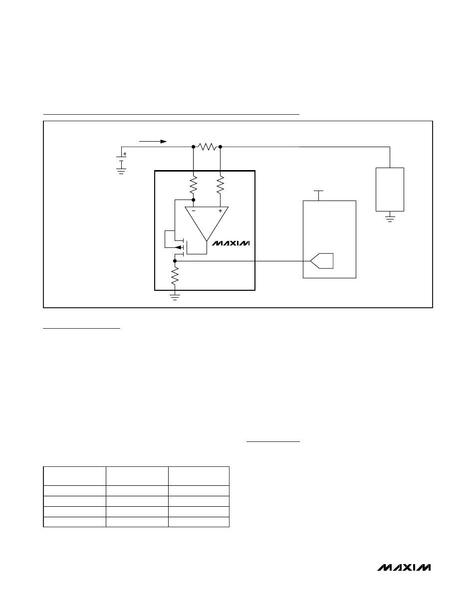
Typical Operating Circuit
V
BATT
= 1.6V TO 28V
R
SENSE
R
1
I
LOAD
R
OUT
R
1
GND
OUT
P
MAX9634
RS+
RS-
ADC
LOAD
µC
V
DD
= 3.3V
10k
Ω