Table 1. mute/shutdown register mapping – Rainbow Electronics MAX5106 User Manual
Page 9
MAX5105/MAX5106
Nonvolatile, Quad, 8-Bit DACs
________________________________________________________________________________________
9
DAC Operation
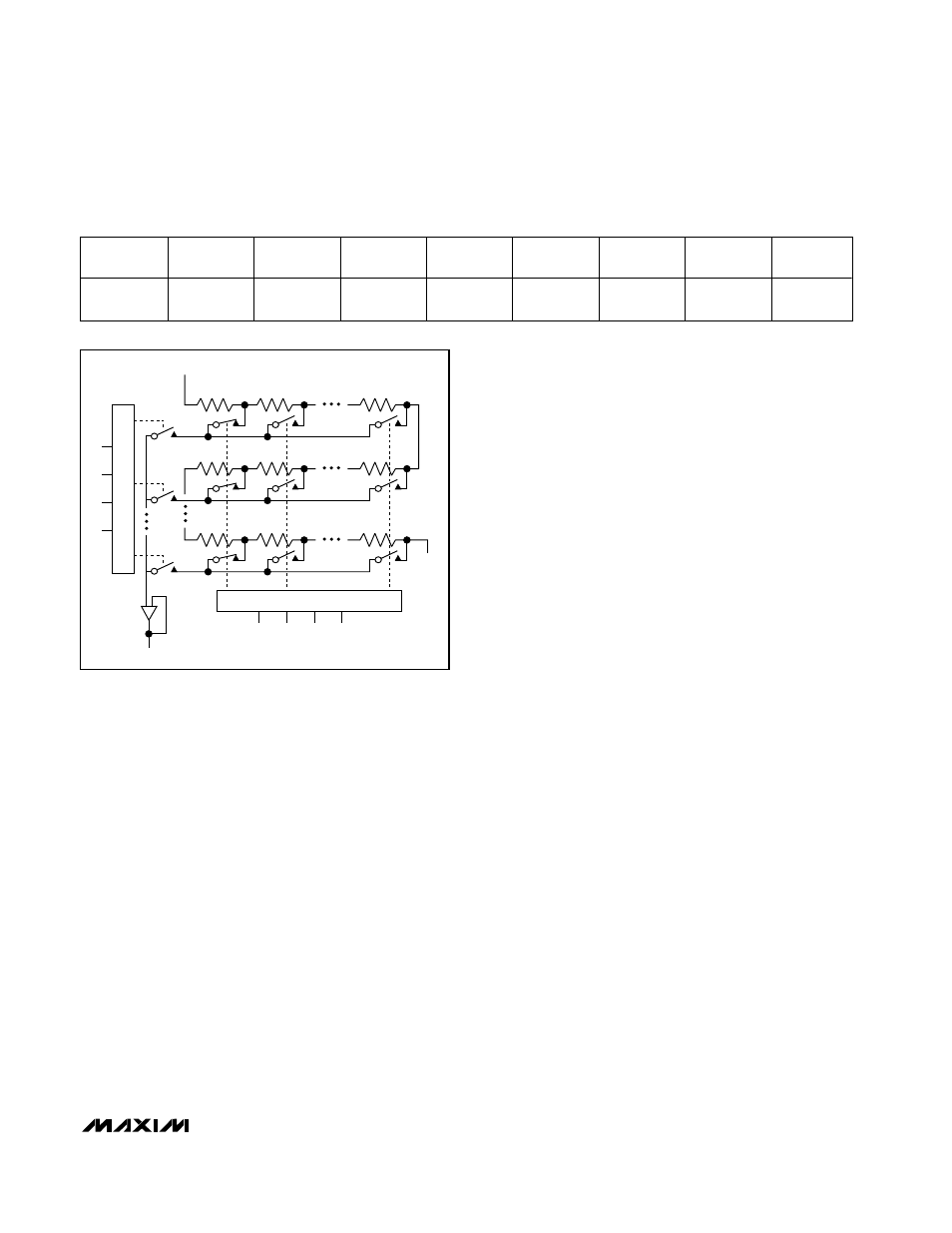
The MAX5105/MAX5106 use a matrix decoding archi-
tecture for the DACs, which saves power in the overall
system. A resistor string placed in a matrix fashion
divides down the difference between the external refer-
ence voltages, V
REFH
and V
REFL
. Row and column
decoders select the appropriate tab from the resistor
string, providing the needed analog voltages. The
resistor string presents a code-independent input
impedance to the reference and guarantees a monoto-
nic output. Figure 1 shows a simplified diagram of one
of the four DACs.
Output Buffer Amplifiers
All MAX5105/MAX5106 analog outputs are internally
buffered by precision unity-gain followers that slew at
about 0.5V/µs. The outputs can swing from GND to
V
DD
. With a V
REFL
_ to V
REFH_
(or V
REFH_
to V
REFL
_)
output transition, the amplifier outputs typically settle to
±1/2LSB in 6µs when loaded with 10k
Ω in parallel with
100pF.
The software mute/shutdown command independently
drives each output to its respective REFL_ voltage
(mute) or to a high-impedance state (shutdown).
Placing all four DACs in shutdown reduces supply cur-
rent to 10µA (max). The MAX5105 also provides an
asynchronous MUTE input, simultaneously driving all
DAC outputs to their respective REFL_ voltages.
Internal EEPROM
The MAX5105/MAX5106 internal EEPROM consists of
five nonvolatile registers that retain the DAC output and
operating states after the device is powered down.
Four registers store data for each DAC, and one stores
the mute and shutdown states for the device.
DAC Registers
The MAX5105/MAX5106 have eight 8-bit DAC regis-
ters, four volatile and four nonvolatile, that store DAC
data. The four volatile DAC registers hold the current
value of each DAC. Data is written to these registers in
two ways: directly from DIN or loaded from the respec-
tive nonvolatile registers (see Serial Input Data Format
and Control Codes). These registers are cleared when
the device is shut down or power is removed.
The four nonvolatile registers retain the DAC values
even after power is removed. Stored data is accessed
in two ways: transferring data to a volatile register to
update the respective DAC output or reading data
through DOUT (see Serial Input Data Format and
Control Codes). On power-up, the device is automati-
cally initialized with data stored in the nonvolatile regis-
ters.
Mute/Shutdown Registers
The MAX5105/MAX5106 have two 8-bit mute/shutdown
registers that store the operating state of each DAC.
The four MSBs hold the mute states, and the four LSBs
hold the shutdown states (Table 1). The volatile regis-
ters hold the current mute/shutdown state of each DAC.
Like the DAC registers, the nonvolatile mute/shutdown
register maintains its data after the device is powered
down, and the contents can be read on DOUT. The
volatile register is initialized with the nonvolatile data on
power-up and can be loaded through DIN or from the
nonvolatile register (see Serial Input Data Format and
Control Codes).
REFH
REFL
R1
R15
R16
R255
R0
D7
D6
D5
D4
DAC
MSB DECODER
D3
D0
D2
D1
LSB DECODER
Figure 1. DAC Simplified Circuit Diagram
Table 1. Mute/Shutdown Register Mapping
Bit in
Register
D7
(MSB)
D6
D5
D4
D3
D2
D1
D0
(LSB)
C o n t r o l lin g
F u n c t io n
Mute
DAC3
Mute
DAC2
Mute
DAC1
Mute
DAC0
Shutdown
DAC3
Shutdown
DAC2
Shutdown
DAC1
Shutdown
DAC0