Rainbow Electronics MAX5106 User Manual
Page 11
MAX5105/MAX5106
Nonvolatile, Quad, 8-Bit DACs
_______________________________________________________________________________________
11
Serial Interface
The MAX5105/MAX5106 communicate with micro-
processors (µPs) through a synchronous, full-duplex 3-
wire interface (Figure 2). Data is sent MSB first and is
transmitted in one 14-bit word. A 4-wire interface adds
a line for RDY/BSY (MAX5105), indicating the status of
the nonvolatile memory. Data is transmitted and
received simultaneously.
Figure 3 shows the detailed serial interface timing. Note
that the clock should be low if it is stopped between
updates. DOUT is high impedance until a valid read
command and address is written to the device.
Serial data is clocked into the 14-bit shift register in an
MSB-first format, with the start-bit, configuration, and
address information preceding the actual DAC data.
Data is clocked in on CLK’s rising edge while CS is low.
CS must be low to enable the device. If CS is high, the
interface is disabled and DOUT remains unchanged.
CS must go low at least 100ns before the first rising
edge of the clock pulse to properly clock in the first bit.
With CS low, data is clocked into the shift register on
the rising edge of the external serial clock.
Serial Input Data Format
and Control Codes
The 14-bit serial input format, shown in Figure 4, com-
prises one start bit, two control bits (C0, C1), three
address bits (A0, A1, A2), and eight data bits (D7–D0).
The 5-bit address/control code configures the DAC as
shown in Table 2.
Nonvolatile Store Command
The nonvolatile store command loads the 8-bit DAC
data into the selected nonvolatile DAC register, or the
DAC operating states into the mute/shutdown non-
volatile register. The nonvolatile store command does
not affect the current DAC outputs or operating states.
Once the control and address bits are clocked in,
RDY/BSY (MAX5105) goes low until the nonvolatile
store operation is complete. For the MAX5106, wait the
maximum 13ms store time before writing a new word to
the device. Do not write new data to the device until
RDY/BSY (MAX5105) returns high, or the 13ms store
time (MAX5106) has elapsed. Figure 5 shows the non-
volatile store command timing diagram.
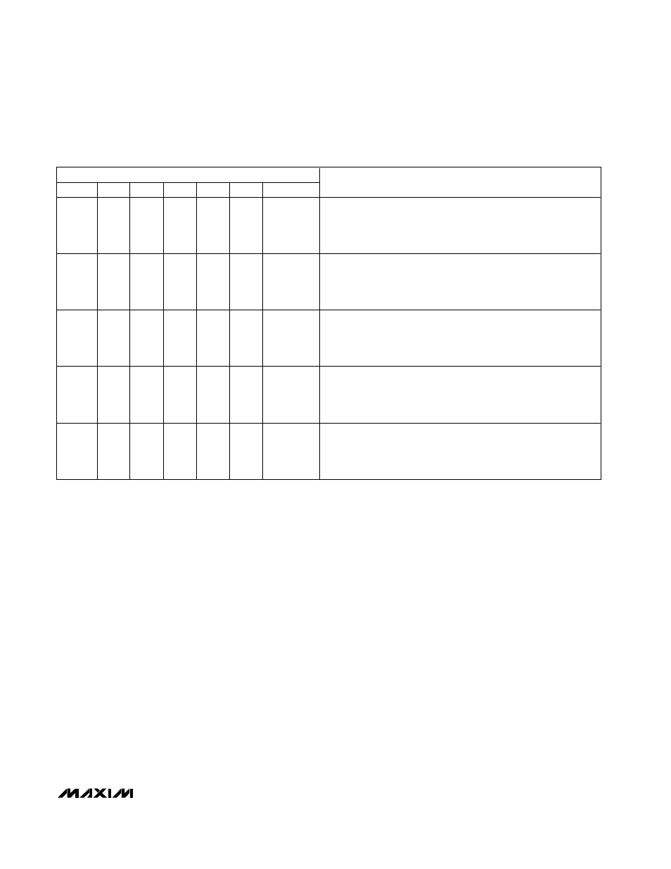
Table 2. Serial Interface Programming Commands (continued)
14-BIT SERIAL WORD
START
C1
C0
A2
A1
A0
D7–D0
FUNCTION
1
1
1
0
0
0
XXXXXXXX
Load DAC0 nonvolatile register. Contents of DAC0 nonvolatile
register are loaded into the corresponding volatile register and
OUT0 updated. D7–D0 are ignored, and all other DAC outputs
remain unchanged.
1
1
1
0
0
1
XXXXXXXX
Load DAC1 nonvolatile register. Contents of DAC1 nonvolatile
register are loaded into the corresponding volatile register and
OUT1 updated. D7–D0 are ignored, and all other DAC outputs
remain unchanged.
1
1
1
0
1
0
XXXXXXXX
Load DAC2 nonvolatile register. Contents of DAC2 nonvolatile
register are loaded into the corresponding volatile register and
OUT2 updated. D7–D0 are ignored, and all other DAC outputs
remain unchanged.
1
1
1
0
1
1
XXXXXXXX
Load DAC3 nonvolatile register. Contents of DAC3 nonvolatile
register are loaded into the corresponding volatile register and
OUT3 updated. D7–D0 are ignored, and all other DAC outputs
remain unchanged.
1
1
1
1
0
0
XXXXXXXX
Load mute/shutdown nonvolatile register. Contents of
mute/shutdown nonvolatile register are loaded into the
mute/shutdown volatile register, and all DACs are placed into their
respective mute/shutdown states. D7–D0 are ignored.