Nonvolatile read command – Rainbow Electronics MAX5106 User Manual
Page 14
MAX5105/MAX5106
Nonvolatile, Quad, 8-Bit DACs
14
______________________________________________________________________________________
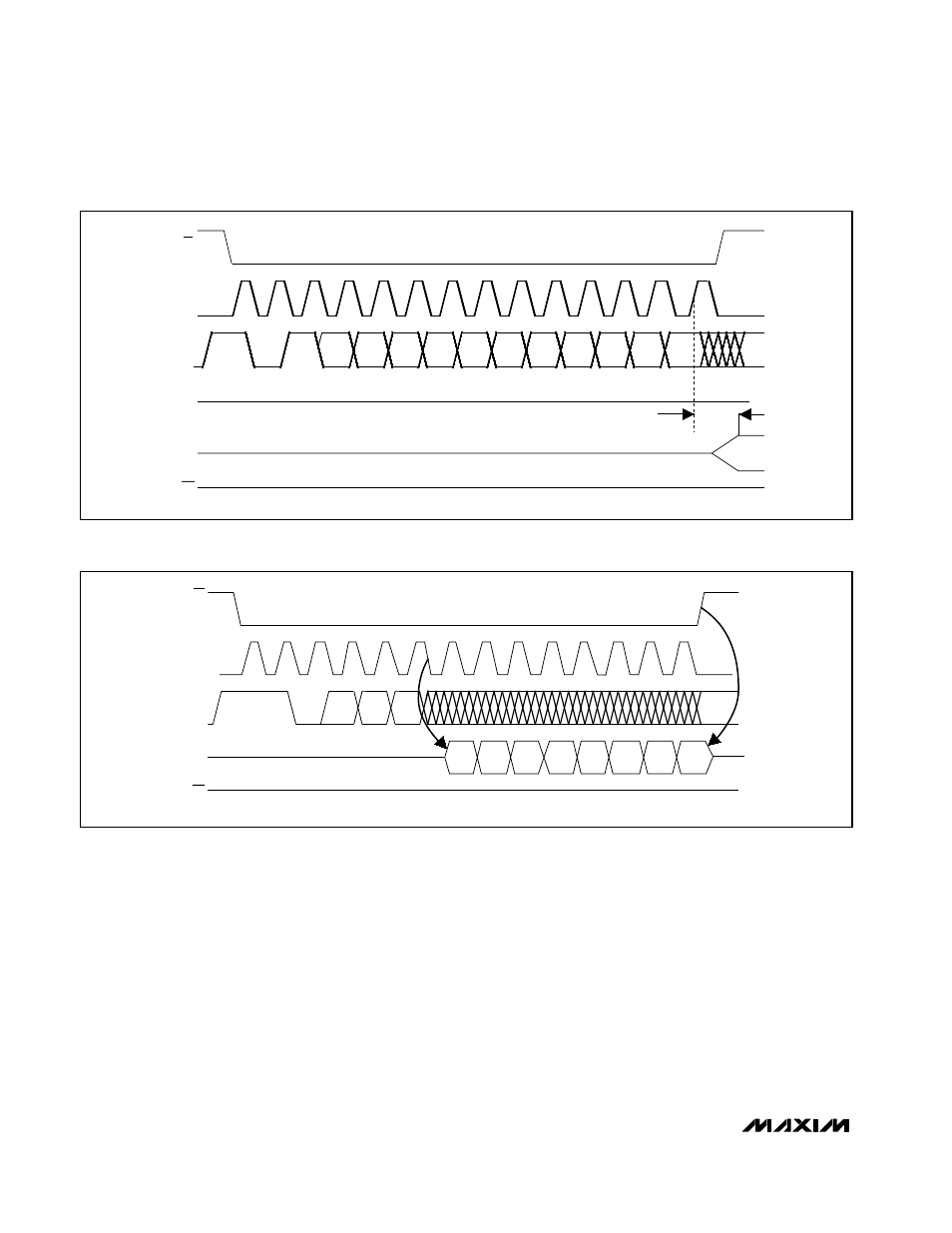
on the rising edge of CLK corresponding to D0. The
register write command does not affect data stored in
the nonvolatile memory. Figure 6 shows the register
write command timing diagram.
Nonvolatile Read Command
The nonvolatile read command makes the data from
the selected nonvolatile register available to external
devices. Data is clocked out on DOUT during the eight
clock cycles following A0. DOUT returns to a high-
impedance state when CS goes high. This command
has no effect on the DAC outputs, operating states, or
contents of the nonvolatile registers. Figure 7 shows the
nonvolatile read command timing diagram. RDY/BSY
remains high while a read is taking place.
D1
t
COS
D0
CS
CLK
DIN
START
C1
C0
DOUT
OUT_
D3
D2
A2
A0
D7
D6
D5
D4
A1
HIGH IMPEDANCE
AT V
DD
(MAX5105 ONLY)
RDY/BSY
Figure 6. Register Write Command Timing Diagram
START
DIN
CLK
DOUT
A2
A0
A1
HIGH IMPEDANCE
D0
D1
D2
D4
D5
D6
D7
D3
AT V
DD
(MAX5105 ONLY)
CI
CO
CS
RDY/BSY
Figure 7. Nonvolatile Read Command Timing Diagram