Detailed description, Pin description – Rainbow Electronics MAX5106 User Manual
Page 8
Detailed Description
The MAX5105/MAX5106 quad, 8-bit DACs feature an
internal, nonvolatile EEPROM, which stores the DAC
states for initialization during power-up. These devices
consist of four resistor string DACs, four rail-to-rail
buffers, a 14-bit shift register, oscillator, power-on reset
(POR) circuitry, and five volatile and five nonvolatile
memory registers (Functional Diagram). The shift regis-
ter decodes the control and address bits, routing the
data to the proper memory registers. Data can be writ-
ten to a selected volatile register, immediately updating
the DAC output, or can be written to a selected non-
volatile register for storage.
The five volatile registers retain data as long as the
device is enabled and powered. Once power is
removed or the device is shut down, the volatile regis-
ters are cleared. The nonvolatile registers retain data
even after power is removed. On power-up, the POR
circuitry and internal oscillator control the transfer of
data from the nonvolatile registers to the volatile regis-
ters, which automatically initializes the device upon
startup. Data can be read from the nonvolatile registers
through DOUT.
MAX5105/MAX5106
Nonvolatile, Quad, 8-Bit DACs
8
_______________________________________________________________________________________
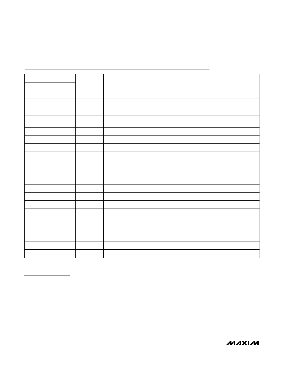
Pin Description
PIN
MAX5105
MAX5106
NAME
FUNCTION
1
1
REFH1
DAC1 High Reference Input
2
2
REFH0
DAC0 High Reference Input
3
3
V
DD
Positive Supply Voltage
4
—
RDY/BSY
Ready/Busy Open-Drain Output. Indicates the state of the nonvolatile memory.
Connect a 100k
Ω pullup resistor from RDY/BSY to V
DD.
5
4
CLK
Serial Clock Input
6
5
CS
Chip Select Input
7
6
DIN
Serial Data Input
8
7
DOUT
Serial Data Output
9
—
MUTE
Mute Input. Drives all DAC outputs to their respective REFL_ voltages.
10
8
GND
Ground. Serves as REFL2 and REFL3 for the MAX5106.
11
9
REFL0
DAC0 Low Reference Input
12
10
REFL1
DAC1 Low Reference Input
13
—
REFL2
DAC2 Low Reference Input
14
—
REFL3
DAC3 Low Reference Input
15
11
OUT3
DAC3 Output
16
12
OUT2
DAC2 Output
17
13
OUT1
DAC1 Output
18
14
OUT0
DAC0 Output
19
15
REFH3
DAC3 High Reference Input
20
16
REFH2
DAC2 High Reference Input