Electrical characteristics (continued) – Rainbow Electronics MAX5106 User Manual
Page 4
MAX5105/MAX5106
Nonvolatile, Quad, 8-Bit DACs
4
_______________________________________________________________________________________
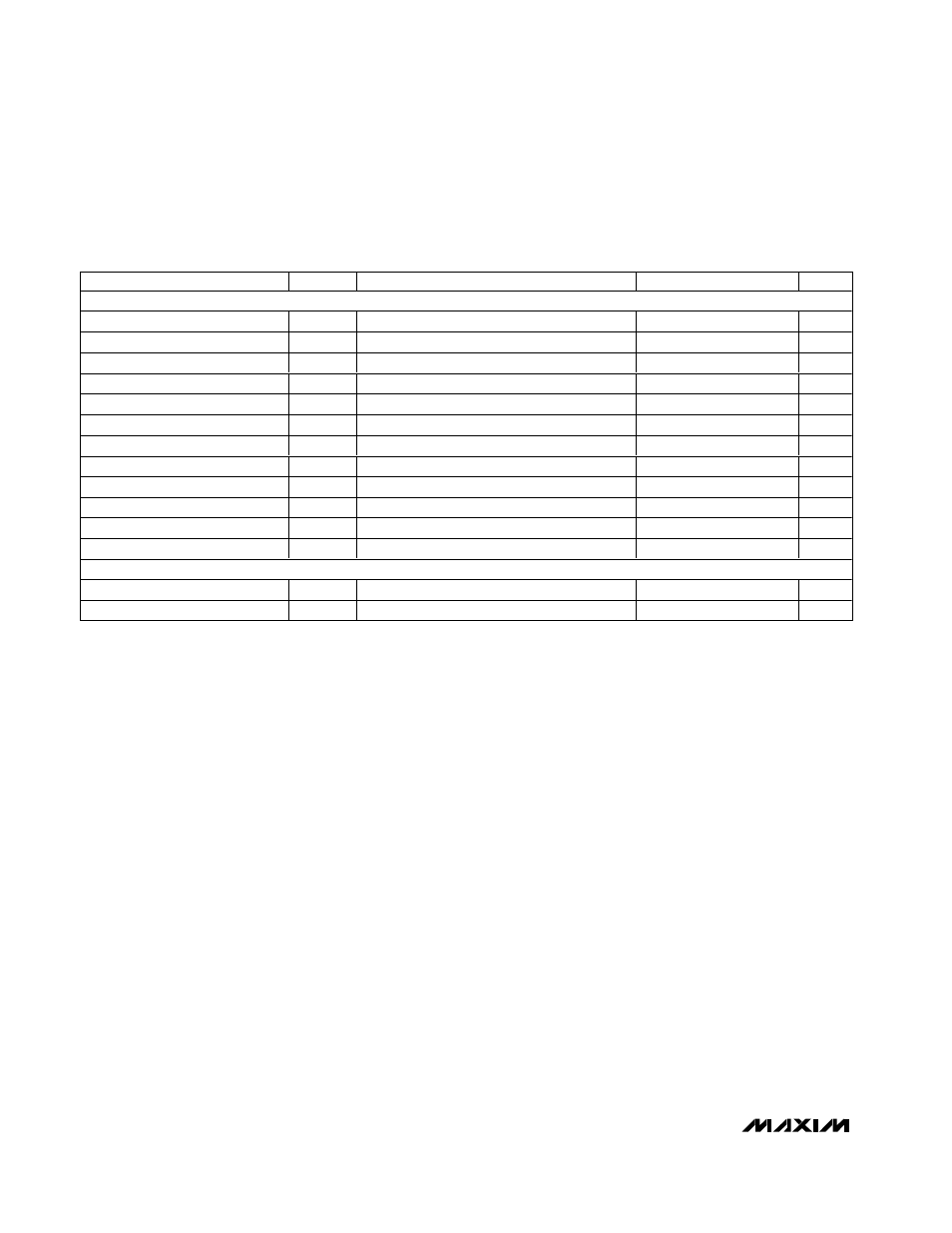
ELECTRICAL CHARACTERISTICS (continued)
(V
DD
= V
REFH_
= +2.7V to +5.5V, GND = V
REFL_
= 0, C
L
= 100pF, T
A
= T
MIN
to T
MAX
, unless otherwise noted. Typical values are at
V
DD
= +3V and T
A
= +25°C.)
PARAMETER
SYMBOL
CONDITIONS
MIN
TYP
MAX
UNITS
DIGITAL TIMING
CLK Period
t
CP
1
µs
CLK High Time
t
CH
300
ns
CLK Low Time
t
CL
300
ns
CS High Time
t
CSHT
150
ns
CS Setup Time
t
CSS
100
ns
CS Hold Time
t
CSH
0
ns
DIN Setup Time
t
DS
100
ns
DIN Hold Time
t
DH
0
ns
CLK to DOUT Valid Time
t
CDV
C
LOAD
= 100pF
1
µs
CLK to DOUT Propagation Delay
t
CD
C
LOAD
= 100pF
1
µs
DOUT Disable Time
t
CSD
C
LOAD
= 100pF
250
ns
Nonvolatile Store Time
t
BUSY
13
ms
NONVOLATILE MEMORY RELIABILITY
Data Retention
MIL STD-883 Test Method 1008
100
Years
Endurance
MIL STD-883 Test Method 1033
100,000
Stores
Note 1: Guaranteed monotonic.
Note 2: Gain error is: [100 x (V
F0(MEAS)
- ZCE - V
F0(IDEAL)
)/V
REFH
]; where V
F0(MEAS)
is the DAC output voltage with input code
F0hex. V
F0(IDEAL)
is the ideal DAC output voltage with input code F0hex (i.e., (V
REFH
- V
REFL
)
× 240/256 + V
REFL
).
Note 3: In the voltage range, 0.5V < V
OUT
_ < V
DD
- 0.5V.
Note 4: Output settling time is measured from the 50% point of the rising edge of last CLK to 1/2LSB of V
OUT
’s final value for a code
transition from 10hex to F0hex. See Figure 4.
Note 5: Channel-to-channel crosstalk is defined as the coupling from one driven reference with input code = FFhex to any other
DAC output with the reference of that DAC at a constant value and input code = 00hex.