Rainbow Electronics MAX9792 User Manual
Page 23
MAX9791/MAX9792
Windows Vista-Compliant Class D Speaker
Amplifiers with DirectDrive Headphone Amplifiers
______________________________________________________________________________________
23
Setting Speaker Amplifier Gain
External input resistors in conjunction with the internal
feedback resistors (R
FSPKR
) set the speaker amplifier
gain of the MAX9791/MAX9792. Set gain by using
resistor R
IN1
as follows (Figure 9):
where A
VSPKR
is the desired voltage gain. An R
IN1
of
20k
Ω yields a gain of 4V/V, or 12dB.
Component Selection
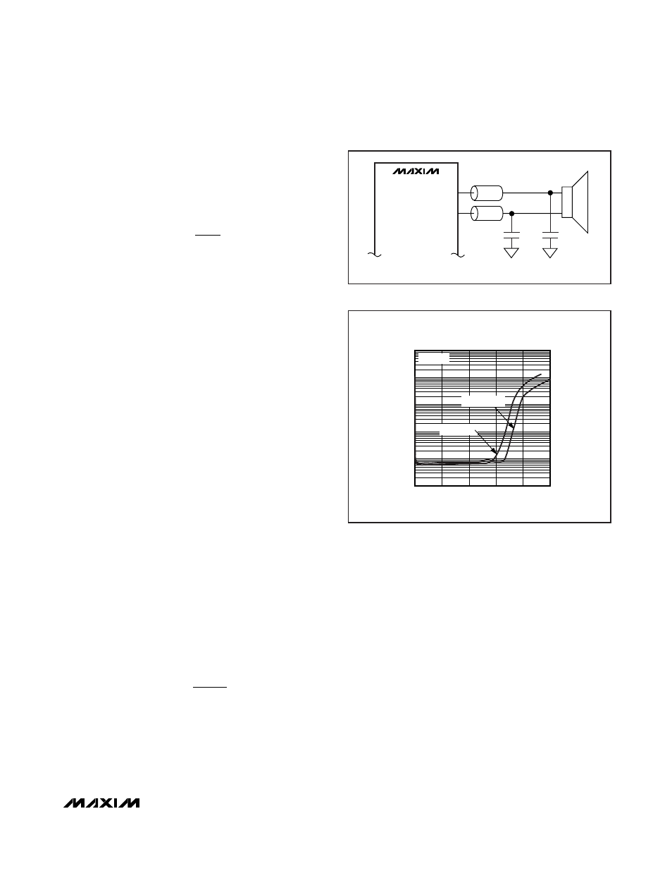
Optional Ferrite Bead Filter
In applications where speaker leads exceed 15cm, use
a filter constructed from a ferrite bead and a capacitor
to ground (Figure 10) to provide additional EMI sup-
pression. Use a ferrite bead with low DC resistance,
high frequency (> 1.2MHz) impedance of 100
Ω to
600
Ω, and rated for at least 1A. The capacitor value
varies based on the ferrite bead chosen and the actual
speaker lead length. Select the capacitor value based
on EMI performance.
Output Power (Headphone Amplifier)
The headphone amplifiers are specified for the worst-
case scenario when both inputs are in phase. Under
this condition, the drivers simultaneously draw current
from the charge pump, leading to a slight loss in head-
room of CPVSS. In typical stereo audio applications, the
left and right signals have differences in both magni-
tude and phase, subsequently leading to an increase in
the maximum attainable output power. Figure 11 shows
the two extreme cases for in and out of phase. In most
cases, the available power lies between these
extremes.
Headphone Amplifier Gain
Gain-Setting Resistors
External input resistors in conjunction with the internal
feedback resistors (R
FHP
) set the headphone amplifier
gain of the MAX9791/MAX9792. Set gain by using
resistor R
IN2
(Figure 4) as follows:
where A
VHP
is the desired voltage gain. An R
IN2
of
40.2k
Ω yields a gain of 1V/V, or 0dB.
Power Supplies
The MAX9791/MAX9792 speaker amplifiers are pow-
ered from PVDD with a range from 4.5V to 5.5V. The
headphone amplifiers are powered from HPVDD and
CPVSS. HPVDD is the positive supply of the headphone
amplifiers and charge pump ranging from 2.7V to 5.5V.
CPVSS is the negative supply of the headphone ampli-
fiers. The charge pump inverts the voltage at HPVDD,
and the resulting voltage appears at CPVSS. AVDD
powers the remainder of the device.
A
k
R
V V
VHP
IN
=
⎛
⎝⎜
⎞
⎠⎟
-
40 2
2
.
/
Ω
A
k
R
V V
VSPKR
IN
=
⎛
⎝⎜
⎞
⎠⎟
-4
20
1
Ω
/
MAX9791A/B
MAX9792A
L1*
L2*
330pF
330pF
*L1 = L2 = WÜRTH 742792040
Figure 10. Optional Ferrite Bead Filter
TOTAL HARMONIC DISTORTION + NOISE
vs. OUTPUT POWER (HEADPHONE MODE)
OUTPUT POWER (mW)
THD+N (%)
200
150
100
50
0.01
0.1
1
10
100
0.001
0
250
R
L
= 32
Ω
OUT OF PHASE
IN PHASE
Figure 11. Output Power vs. Supply Voltage with Inputs In/Out
of Phase; 32W Load Conditions and 3.5dB Gain