Detailed description, Max9792 pin description – Rainbow Electronics MAX9792 User Manual
Page 17
MAX9791/MAX9792
Windows Vista-Compliant Class D Speaker
Amplifiers with DirectDrive Headphone Amplifiers
______________________________________________________________________________________
17
Detailed Description
The MAX9791 combines a stereo 2W Class D power
amplifier, a stereo 175mW DirectDrive headphone
amplifier, and a 120mA LDO linear regulator in a single
device. The MAX9792 combines a mono 3W Class D
power amplifier, a stereo 175mW DirectDrive head-
phone amplifier, and a 120mA LDO linear regulator in a
single device.
The MAX9791/MAX9792 feature wake-on-beep detec-
tion, comprehensive click-and-pop suppression, low-
power shutdown mode, and excellent RF immunity.
These devices incorporate an integrated LDO that
serves as a clean power supply for CODEC or other cir-
cuits. The MAX9791/MAX9792 are Windows Vista
Premium compliant. See Table 1 for a comparison of the
Windows Vista Premium specifications and MAX9791/
MAX9792 specifications.
The MAX9791/MAX9792 feature spread-spectrum mod-
ulation and active emission limiting circuitry that offers
significant improvements to switch-mode amplifier tech-
nology. These devices offer Class AB performance with
Class D efficiency in a minimal board-space solution.
The headphone amplifiers use Maxim’s patented
DirectDrive architecture to eliminate the bulky output
DC-blocking capacitors required by traditional head-
phone amplifiers. A charge pump inverts the positive
supply (HPVDD) to create a negative supply (CPVSS).
The headphone amplifiers operate from these bipolar
supplies with their outputs biased about GND. The ben-
efit of the GND bias is that the amplifier outputs no
longer have a DC component (typically V
DD
/2). This
feature eliminates the large DC-blocking capacitors
required with conventional headphone amplifiers to
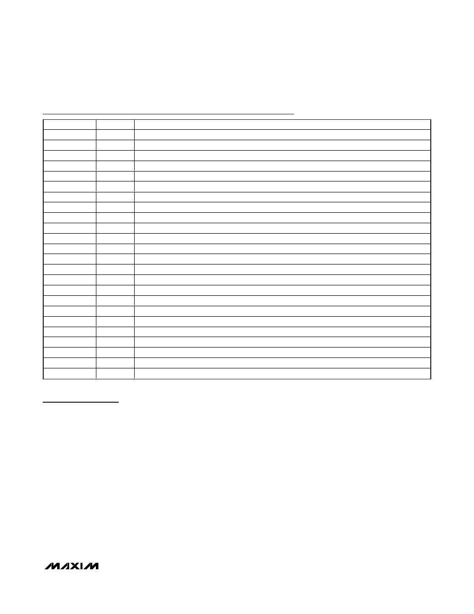
MAX9792 Pin Description
PIN
NAME
FUNCTION
1, 5
GND
Signal Ground. Star connect to PGND.
2
HP_INR
Right-Channel Headphone Amplifier Input
3
HP_INL
Left-Channel Headphone Amplifier Input
4
COM
Common-Mode Voltage Sense Input
6
LDO_OUT
LDO Output. Bypass with two 1µF ceramic low ESR capacitors to GND.
7
AVDD
Positive Power Supply and LDO Input. Bypass with a 0.1µF and two 1µF capacitors to GND.
8
LDO_EN
LDO Enable. Connect LDO_EN to AVDD to enable the LDO.
9
HPR
Right-Channel Headphone Amplifier Output
10
HPL
Left-Channel Headphone Amplifier Output
11
SENSE
Headphone Ground Sense
12
CPVSS
Headphone Amplifier Negative Power Supply. Connect a 1µF capacitor between CPVSS and PGND.
13
C1N
Charge-Pump Flying Capacitor Negative Terminal. Connect a 1µF capacitor between C1P and C1N.
14
CPGND
Charge-Pump Ground. Connect directly to PGND plane.
15
C1P
Charge-Pump Flying Capacitor Positive Terminal. Connect a 1µF capacitor between C1P and C1N.
16
HPVDD
H ead p hone Am p l i fi er P osi ti ve P ow er S up p l y. C onnect a 10µF cap aci tor b etw een H P V D D and P GN D .
17, 26
PVDD
Speaker Amplifier Power-Supply Input. Bypass with a 0.1µF capacitor to PGND.
18, 25
OUT-
Speaker Amplifier Output, Negative Phase
19, 24
OUT+
Speaker Amplifier Output, Positive Phase
20, 23
PGND
Power Ground. Star connect to GND.
21
BEEP
PC Beep Input. Connect to GND if beep detection function is disabled.
22
HP_EN
Active-High Headphone Amplifier Enable
27
SPKR_EN Active-Low Speaker Amplifier Enable
28
SPKR_IN
Speaker Amplifier Input
—
EP
Exposed Pad. Connect to GND.