Electrical, 1 40 way hirose pin descriptions – Rainbow Electronics DAB-WLS-C01 (WiFi) User Manual
Page 7
DSH_WISMC01_1v2 WISM 40 pin TCP-IP Data Sheet.doc © 2007 EZURiO Ltd
Page 7
5.
Electrical
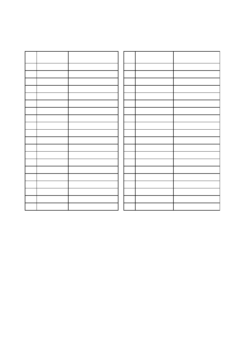
5.1 40 way Hirose Pin Descriptions
The Hirose DF12C board-to-board connector on the module is a 40-pin double-row receptacle.
The table below defines the pin functions. The pin-out is as viewed from the underside of the Module.
Pin
No.
Signal Description
Pin
No.
Signal Description
1
ADC 0
3.0 V Max
2
GPIO1
I/O for Host.
3
ADC 1
3.0 V Max
4
GPIO2
I/O for Host
5
WLAN_ACTIVE Output
6
UART_RI
Ring or GPIO12
7
N/C
8
UART_DCD
DCD or GPIO13
9
N/C
10
UART_DSR
DSR or GPIO10
11
GND
12
UART_DTR
DTR or GPIO11
13
RESET
Reset Input
14
GPIO4
I/O for Host
15
GND
16
GPIO5
I/O for Host
17 N/C
18 GND
19
UART_CTS
Clear to Send Input
20
N/C
21
UART_TX
Transmit Data Output
22
WAKEUP
Reserved
23
UART_RTS
Request to Send Output 24
BT_PRIORITY
Input
25
UART_RX
Receive Data Input
26
N/C
27 VCC_3V
3.0V
Monitor
28 VCC_5V
Supply
29 VCC_5V
Supply
30 GND
31 VCC_5V
Supply
32 N/C
33
GPIO6
I/O for Host
34
N/C
35
GPIO7
I/O for Host
36
GND
37
GPIO8
I/O for Host
38
GND
39
GPIO9
I/O for Host
40
BT_STATE
Input
Notes:
The reset circuitry within the module incorporates a brown-out detector. The reset pin has a fixed
10kOhm pull down resistor to ground, followed by a 10kOhm resistor feeding the base of a transistor.
GPIO lines can be configured through software to be either inputs or outputs. At reset, all GPIO lines
are configured as inputs.
UART_RX, UART_TX, UART_CTS, UART_RTS, UART_RI, UART_DCD, UART_DTR and UART_DSR are all
3.0v level logic. When the signal sits at 3.0V it is de-asserted. When the signal is at 0V it is asserted.
UART_RX, UART_TX, UART_CTS, UART_RTS are controlled directly by the module. The operation of
UART_RI, UART_DCD and UART_DTR is user programmable under script control.
Pin 27 (VCC_3V) may only be used for monitoring purposes. It must not be used as a current source.
Pin 22 (WAKEUP) will be used for future powersave functionality. It has an internal 100kOhm pull-up.
ADC inputs (pins 1 and 3) are read using UWscript functions.
UART_DSR is used to enable autorun. After power-up it can be used as GPIO. See Section 8.2.
Pins marked N/C may have internal connections within the module and should not be connected to any
external circuitry.