Smbus digital interface – Rainbow Electronics MAX6636 User Manual
Page 7
ed, and the temperature registers are not updated. The
previous data is not changed and remains available.
SMBus Digital Interface
From a software perspective, the MAX6636 appears as
a series of 8-bit registers that contain temperature mea-
surement data, alarm threshold values, and control bits.
A standard SMBus-compatible, 2-wire serial interface is
used to read temperature data and write control bits
and alarm threshold data. The same SMBus slave
address also provides access to all functions.
The MAX6636 employs four standard SMBus protocols:
write byte, read byte, send byte, and receive byte
(Figure 2). The shorter receive byte protocol allows
quicker transfers, provided that the correct data regis-
ter was previously selected by a read byte instruction.
Use caution with the shorter protocols in multimaster
systems, since a second master could overwrite the
command byte without informing the first master. Figure
3 is the SMBus write-timing diagram and Figure 4 is the
SMBus read-timing diagram.
The remote diode 1 measurement channel provides 11
bits of data (1 LSB = 0.125°C). All other temperature-
measurement channels provide 8 bits of temperature
data (1 LSB = 1°C). The 8 most significant bits (MSBs)
can be read from the local temperature and remote
temperature registers. The remaining 3 bits for remote
diode 1 can be read from the extended temperature
MAX6636
7-Channel Precision Temperature Monitor
_______________________________________________________________________________________
7
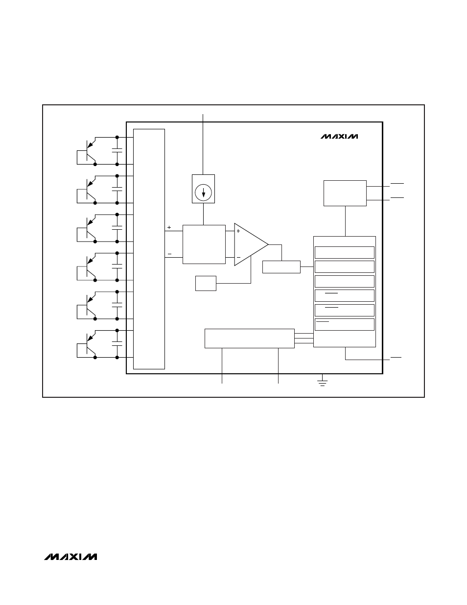
Figure 1. Internal Block Diagram
DXP1
DXN1
DXP2
DXN2
DXP3
DXN3
DXP4
DXN4
DXP5
DXN5
DXP6
DXN6
INPUT
BUFFER
10/100
μA
V
CC
REF
COUNT
COUNTER
COMMAND BYTE
REMOTE TEMPERATURES
LOCAL TEMPERATURES
REGISTER BANK
ALERT THRESHOLD
OVERT THRESHOLD
ALERT RESPONSE ADDRESS
ALARM
ALU
ADC
SMBus
INTERFACE
MAX6636
SCL
SDA
OVERT
AVERT
STBY