Register description proximity light sensing, Led driver – Rainbow Electronics MAX44000 User Manual
Page 9
_______________________________________________________________________________________ 9
MAX44000
Ambient and Infrared Proximity Sensor
Register Description
Proximity Light Sensing
The proximity sensing uses an external, pulsed infrared
LED source to emit controlled amounts of infrared radia-
tion. When an external object reflects back some of this
infrared radiation back to the IC, it is detected by the
integrated light detector. The amount of reflected light
detected is then used to determine the object’s proximity
to the sensor.
It is important to take account for the fact that different
objects at the same distance from the sensor can reflect
different amounts of infrared radiation depending on
their texture and color.
The IC includes on-chip ambient cancellation circuitry
in the receive path of the infrared proximity sensor. This
scheme allows the part to operate in the presence of
large amounts of DC IR radiation. Due to the use of a
single-pulse technique in pulsing the external infrared
LED, the chip is also immune to fixed-frequency external
infrared radiation such as from remote controls, elec-
tronic ballasts, etc., leading to more reliable infrared
proximity sensor operation.
LED Driver
The IC features a LED driver that delivers a pulsed cur-
rent at the output. The pulse amplitude is programmable
through the I
2
C interface from 0 to 110mA in steps of
10mA. A low-voltage compliance of DRV pin allows IR
LEDs to be powered from lower voltage rails, possibly
even a 1.8V rail. High-current drive accuracy improves
performance by eliminating part-to-part variation.
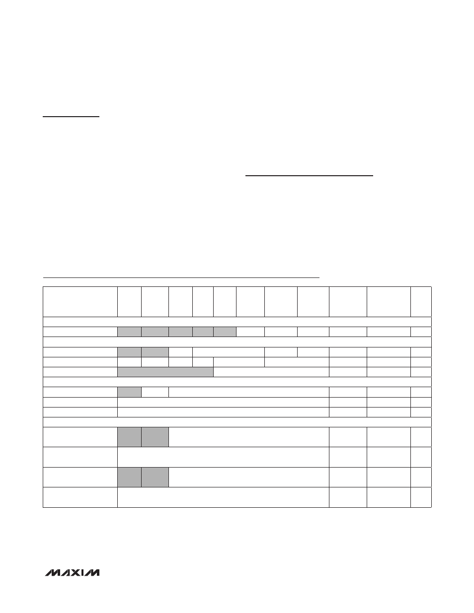
REGISTER
B7
B6
B5
B4
B3
B2
B1
B0
REGISTER
ADDRESS
POWER-ON
RESET
STATE
R/W
STATUS
Interrupt Status
PWRON PRXINTS ALSINTS
0x00
0x04
R
CONFIGURATION
Main Configuration
TRIM
MODE[2:0]
PRXINTE ALSINTE
0x01
0x24
R/W
Receive Configuration
1
1
1
1
ALSTIM[1:0]
ALSPGA[1:0]
0x02
0x00
R/W
Transmit Configuration
DRV[3:0]
0x03
0x00
R/W
ADC DATA
ADC High Byte (ALS
)
OFL
ALSDATA[13:8]
0x04
0x00
R
ADC Low Byte (ALS
)
ALSDATA[7:0]
0x05
0x00
R
ADC Byte (PROX)
PRXDATA[7:0]
0x16
0x00
R
THRESHOLD SET
ALS Upper Threshold
(High Byte
)
UPTHR[13:8]
0x06
0x00
R/W
ALS Upper Threshold
(Low Byte)
UPTHR[7:0]
0x07
0x00
R/W
ALS Lower Threshold
(High Byte)
LOTHR[13:8]
0x08
0x00
R/W
ALS Lower Threshold
(Low Byte)
LOTHR[7:0]
0x09
0x00
R/W