Rainbow Electronics MAX44000 User Manual
Page 20
20 _____________________________________________________________________________________
MAX44000
Ambient and Infrared Proximity Sensor
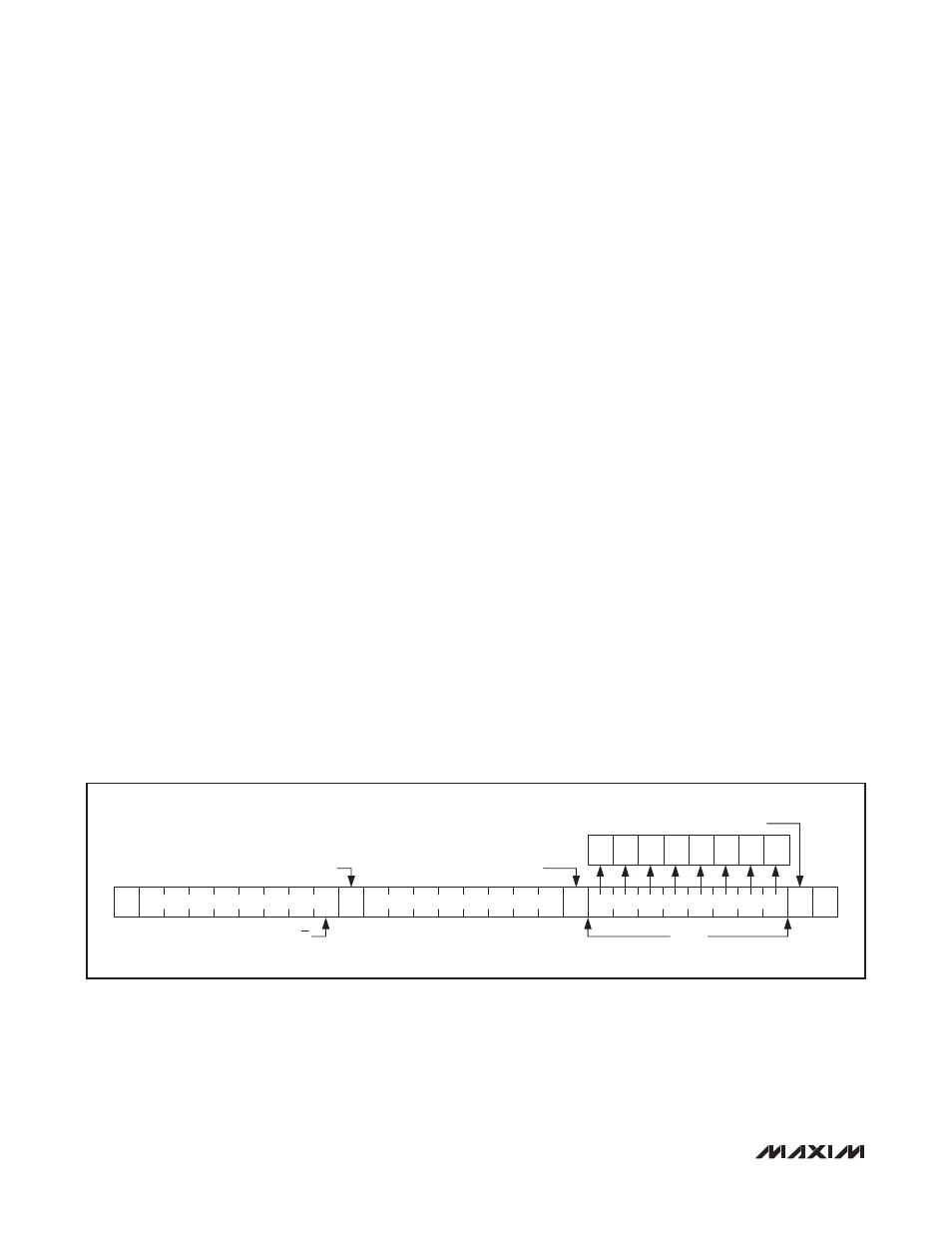
Write Data Format
A write to the IC includes transmission of a START condi-
tion, the slave address with the R/W bit set to 0, 1 byte
of data to configure the internal register address pointer,
one or more bytes of data, and a STOP condition. Figure
7 illustrates the proper frame format for writing 1 byte of
data to the IC.
The slave address with the R/W bit set to 0 indicates
that the master intends to write data to the IC. The IC
acknowledges receipt of the address byte during the
master-generated ninth SCL pulse.
The second byte transmitted from the master configures
the IC’s internal register address pointer. The pointer
tells the IC where to write the next byte of data. An
acknowledge pulse is sent by the IC upon receipt of the
address pointer data.
The third byte sent to the IC contains the data that is
written to the chosen register. An acknowledge pulse
from the IC signals receipt of the data byte. Figure 8 illus-
trates how to write to multiple registers with one frame.
The master signals the end of transmission by issuing a
STOP condition.
Read Data Format
Send the slave address with the R/W bit set to 1 to initi-
ate a read operation. The IC acknowledges receipt of
its slave address by pulling SDA low during the ninth
SCL clock pulse. A START command followed by a read
command resets the address pointer to register 0x00.
The first byte transmitted from the IC is the contents of
register 0x00. Transmitted data is valid on the rising edge
of the master-generated serial clock (SCL). The address
pointer autoincrements after each read data byte. This
autoincrement feature allows all registers to be read
sequentially within one continuous frame. A STOP condi-
tion can be issued after any number of read data bytes.
If a STOP condition is issued followed by another read
operation, the first data byte to be read is from register
0x00 and subsequent reads autoincrement the address
pointer until the next STOP condition. The address
pointer can be preset to a specific register before a read
command is issued. The master presets the address
pointer by first sending the IC’s slave address with the
R/W bit set to 0 followed by the register address. A
Repeated START condition is then sent, followed by the
slave address with the R/W bit set to 1. The IC trans-
mits the contents of the specified register. The address
pointer autoincrements after transmitting the first byte.
Attempting to read from register addresses higher than
0xFF results in repeated reads of 0xFF. Note that 0xF6
to 0xFF are reserved registers. The master acknowl-
edges receipt of each read byte during the acknowledge
clock pulse. The master must acknowledge all correctly
received bytes except the last byte. The final byte must
be followed by a not acknowledge from the master and
then a STOP condition. Figure 8 illustrates the frame
format for reading 1 byte from the IC. Figure 9 illustrates
the frame format for reading two registers consecutively
without a STOP condition in between reads.
Figure 7. Writing 1 Byte of Data to the IC
A
0
SLAVE ADDRESS
REGISTER ADDRESS
DATA BYTE
ACKNOWLEDGE FROM MAX44000
R/W
1 BYTE
ACKNOWLEDGE FROM MAX44000
ACKNOWLEDGE FROM MAX44000
B1
B0
B3
B2
B5
B4
B7
B6
S
A
A
P