Table 1. ambient adc conversion time, Table 2. ambient light measurement gain, Table 3. led drive current settings – Rainbow Electronics MAX44000 User Manual
Page 13
______________________________________________________________________________________ 13
MAX44000
Ambient and Infrared Proximity Sensor
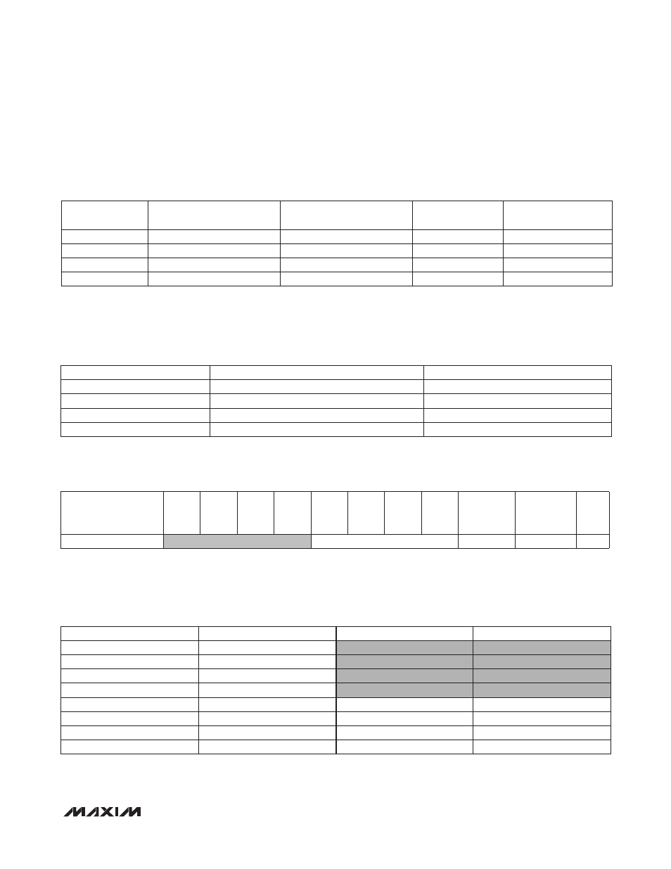
Ambient ADC Conversion Time (ALSTIM)
The 2-bit ALSTIM[1:0] sets the integration time for ALS ADC conversion, as shown in Table 1.
Table 1. Ambient ADC Conversion Time
Ambient Light Measurement Gain (ALSPGA)
The 2-bit ALSPGA[1:0] sets the gain of the ambient light sensing measurement according to Table 2.
Table 2. Ambient Light Measurement Gain
Transmit Configuration Register (0x03)
This register controls the driver current setting and is used when the Proximity channel is enabled.
LED Drive Current Setting (DRV)
The 4 bits of DRV set the LED drive current according to Table 3.
Table 3. LED Drive Current Settings
ALSTIM[1:0]
INTEGRATION TIME (ms)
FULL-SCALE ADC
COUNTS
BIT RESOLUTION
RELATIVE LSB SIZE
00
100
16,384
14
1x
01
25
4096
12
4x
10
6.25
1024
10
16x
11
1.5625
256
8
64x
ALSPGA[1:0]
LUX/LSB
RELATIVE LSB SIZE
00
0.03125
1x
01
0.125
4x
10
0.5
16x
11
4
128x
REGISTER
B7
B6
B5
B4
B3
B2
B1
B0
REGISTER
ADDRESS
POWER-ON
RESET
STATE
R/W
Transmit Configuration
DRV[3:0]
0x03
0x00
R/W
DRV[3:0]
LED CURRENT (mA)
DRV[3:0]
LED CURRENT (mA)
0000
LED driver disabled
1000
40
0001
10
1001
50
0010
20
1010
60
0011
30
1011
70
0100
40
1100
80
0101
50
1101
90
0110
60
1110
100
0111
70
1111
110