Rainbow Electronics MAX44000 User Manual
Page 15
______________________________________________________________________________________ 15
MAX44000
Ambient and Infrared Proximity Sensor
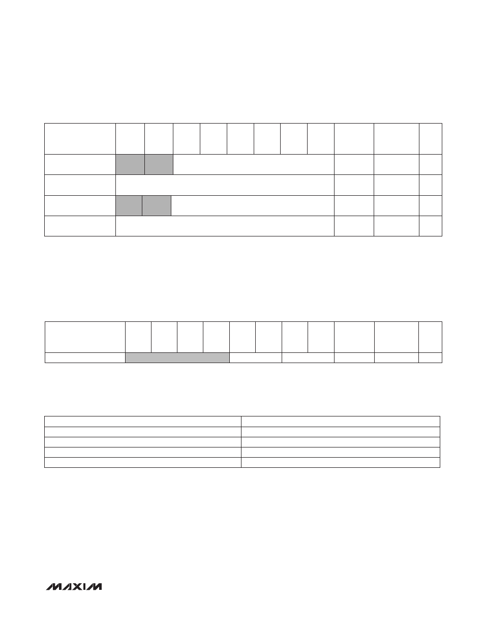
ALS Interrupt Threshold Registers (0x06–0x09)
ALS/PROX Threshold Persist Timer Register (0x0A)
The MAX44000 incorporates a persist function that allows the users to set the number of consecutive triggers before
interrupt. PRXPST[1:0] and ALSPST[1:0] set one of four persist values that control how readily the interrupt logic reacts
to a detected event. This feature is added to reduce false or nuisance interrupts.
When ALSPST[1:0] is set to 00, and the ALSINTE bit is set to 1, the first time an ALS interrupt event is detected, the
ALSINTE interrupt bit is set and the INT pin goes low. If ALSPST[1:0] is set to 01, then four consecutive interrupt events
must be detected on four consecutive measurement cycles. Similarly, if ALSPST[1:0] is set to 10, or 11, then 8 or 16
consecutive interrupts must be detected. If there is an intervening measurement cycle where no interrupt is detected,
then the count is reset to zero. The proximity interrupt function is managed in the same way with PRXPST[1:0].
The ALS upper threshold and ALS lower threshold (UPTHR[13:0] and LOTHR[13:0]) set the window limits that are used
to trigger an ALS interrupt. It is important to set these values according to the selected bit resolution/integration time
chosen for the ALS measurement based on the ALSTIM[1:0] and ALSPGA[1:0] settings. The upper 2 bits are always
ignored. If the INTE bit is set, and the lux level is greater or lower than the respective thresholds for a period greater
than that defined by the ALSPST persist time, the INTS bit in the Status register is set and the INT pin is pulled low.
REGISTER
B7
B6
B5
B4
B3
B2
B1
B0
REGISTER
ADDRESS
POWER-ON
RESET
STATE
R/W
Threshold Persist Timer
PRXPST[1:0]
ALSPST[1:0]
0x0A
0x00
R/W
PRXPST[1:0] OR ALSPST[1:0]
NO. OF CONSECUTIVE TRIGGERS BEFORE INTERRUPT
00
1
01
2
10
4
11
16
REGISTER
B7
B6
B5
B4
B3
B2
B1
B0
REGISTER
ADDRESS
POWER-ON
RESET
STATE
R/W
ALS Upper Threshold
(High Byte)
UPTHR[13:8]
0x06
0x00
R/W
ALS Upper Threshold
(Low Byte)
UPTHR[7:0]
0x07
0x00
R/W
ALS Lower Threshold
(High Byte)
LOTHR[13:8]
0x08
0x00
R/W
ALS Lower Threshold
(Low Byte)
LOTHR[7:0]
0x09
0x00
R/W