Rainbow Electronics MAX44000 User Manual
Page 14
14 _____________________________________________________________________________________
MAX44000
Ambient and Infrared Proximity Sensor
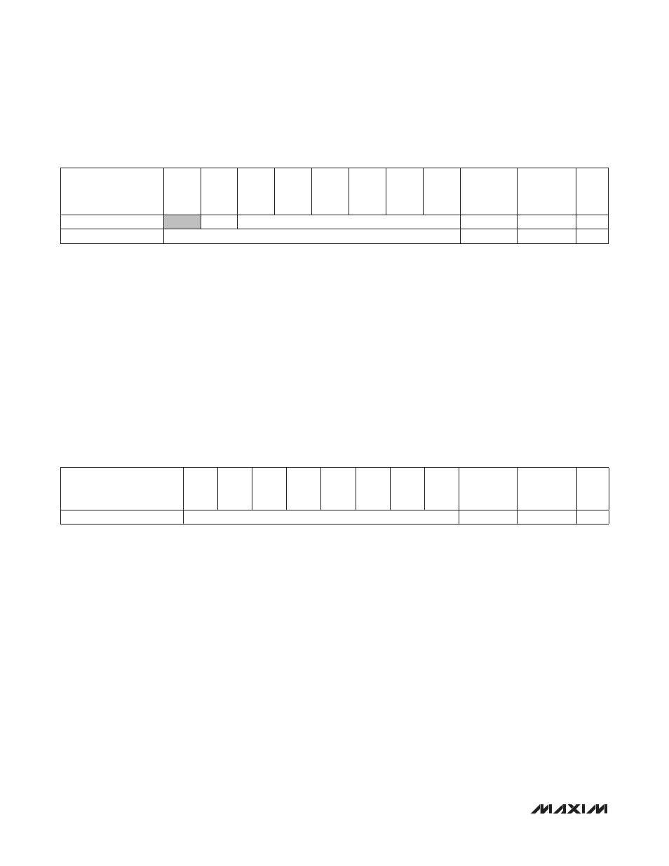
The 2 bytes here (ALSDATA[13:0]) hold the results of the ALS signal conversion. The resolution and bit length of the
result is controlled by the value of ALSTIM[1:0] and ALSPGA[1:0] bits. The result is always right justified in the two
registers, and the unused high bits are zero.
OFL indicates an overflow condition on the ALS channel. If this occurs, set the ALS range (ALSPGA[1:0]) to a higher
range. If the OFL bit is set to 1 (there is an overflow condition), and the ALSINTE bit is set to 1 (enabled), then the
ALSINTS bit is set to 1 and the INT pin is pulled low.
The data in this register could be the green channel, infrared channel, or ALS readings (green channel, infrared chan-
nel readings), depending on the mode selected by the user.
Internal update of these two registers is disabled during I
2
C read operations to ensure proper data handoff between
the ADC and the I
2
C registers. Update of the I
2
C registers is resumed once the master sends a STOP (P) command.
Therefore, when reading the 2 bytes of this register, the master should not send a STOP command between the 2-byte
reads. Instead, a Repeated START (Sr) command should be used. The exact read sequence using the Repeated
START command is shown in the I
2
C Serial Interface section.
ALS Data Register (0x04, 0x05)
PROX Data Registers (0x15, 0x16)
The byte here (PRXDATA[7:0]) hold the results of the proximity receive signal conversion. Internal update of the register
is disabled during I
2
C read operations to ensure proper data handoff between the ADC and the I
2
C registers. Update
of the I
2
C registers is resumed once the master sends a STOP command.
REGISTER
B7
B6
B5
B4
B3
B2
B1
B0
REGISTER
ADDRESS
POWER-ON
RESET
STATE
R/W
ADC High Byte (ALS)
OFL
ALSDATA[13:8]
0x04
0x00
R
ADC Low Byte (ALS)
ALSDATA[7:0]
0x05
0x00
R
REGISTER
B7
B6
B5
B4
B3
B2
B1
B0
REGISTER
ADDRESS
POWER-ON
RESET
STATE
R/W
ADC Byte (PROX)
PRXDATA[7:0]
0x16
0x00
R