Rainbow Electronics MAX44000 User Manual
Page 16
16 _____________________________________________________________________________________
MAX44000
Ambient and Infrared Proximity Sensor
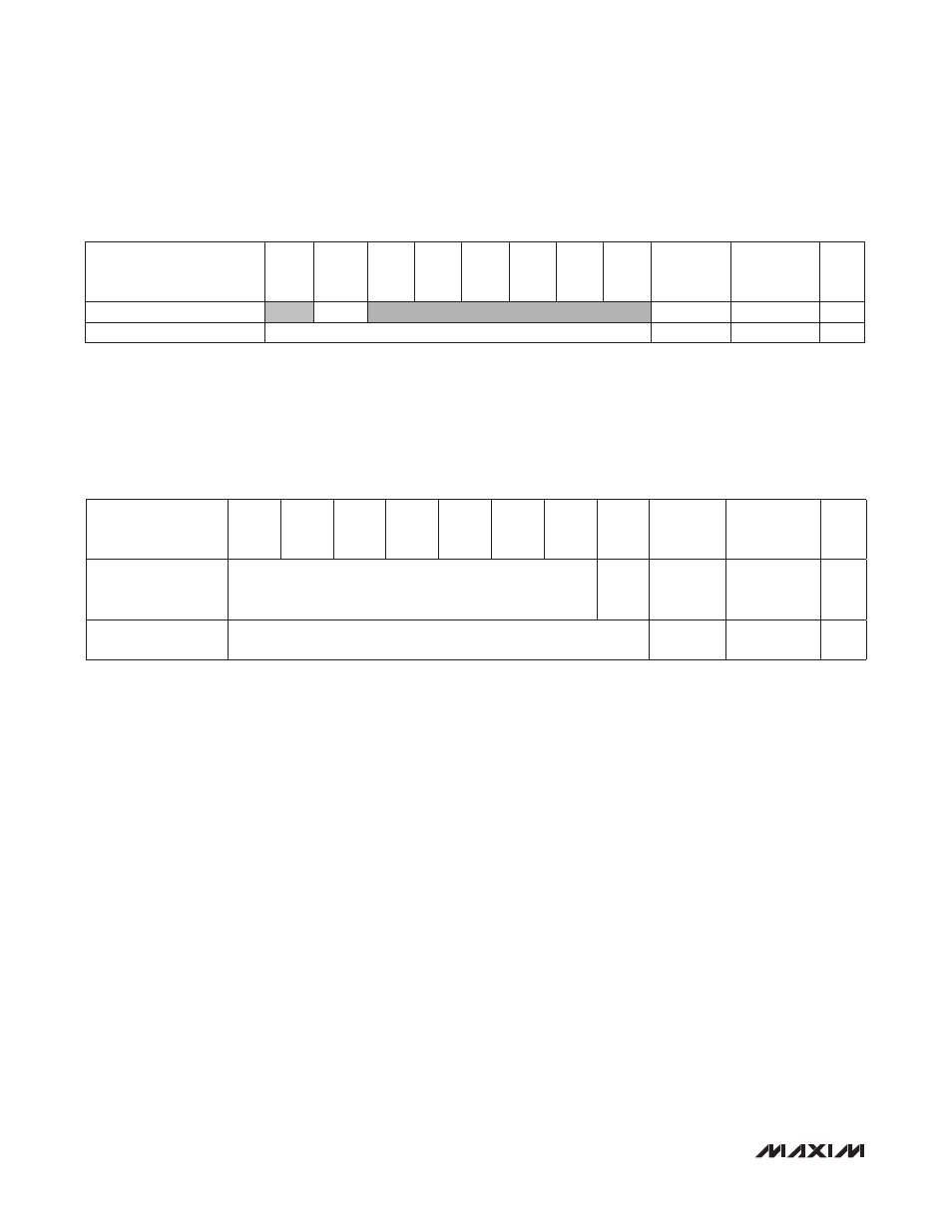
Proximity Threshold Registers (0x0B, 0x0C)
The value set by PRXTHR[7:0] in combination with the ABOVE bit controls the operation of the proximity interrupt func-
tion. If the ABOVE bit is set to 1, the proximity interrupt has been enabled (PRXINTE = 1), and the result of a proximity
measurement is greater than the value stored in PRXTHR[7:0], then a proximity interrupt event is recorded. The inter-
rupt bit is set subject to count conditions set by PRXPST[1:0]. Similarly, if the ABOVE bit is set to 0, then an interrupt
event is recorded if the result of a proximity measurement is less than value stored in PRXTHR[7:0].
Digital Gain Trim Registers (0x0F, 0x10)
Note: Values read from TRIM_GAIN_ registers are the complements of the written value. This is true for reading both the factory-
programmed values and the customer-programmed values.
TRIM_GAIN_GREEN[6:0] is used to modify the gain of the green channel.
TRIM_GAIN_IR[8:0] is used to modify the gain of the IR channel.
To tell the part to use the values written to this register, set the TRIM bit to 0 in the Main Configuration register after
writing new values to these registers.
REGISTER
B7
B6
B5
B4
B3
B2
B1
B0
REGISTER
ADDRESS
POWER-ON
RESET
STATE
R/W
PROX Threshold Indicator
ABOVE
0x0B
0x00
R/W
PROX Threshold
PRXTHR[7:0]
0x0C
0x00
R/W
REGISTER
B7
B6
B5
B4
B3
B2
B1
B0
REGISTER
ADDRESS
POWER-ON
RESET
STATE
R/W
Digital Gain Trim of
Green Channel
TRIM_GAIN_GREEN[6:0]
TRIM_
GAIN_
IR[0]
0x0F
0x80
R/TW
Digital Gain Trim of
Infrared Channel
TRIM_GAIN_IR[8:1]
0x10
0x80
R/TW