Applications information – Rainbow Electronics MAX16820 User Manual
Page 7
Undervoltage Lockout (UVLO)
The MAX16819/MAX16820 include a 4.5V undervoltage
lockout (UVLO) with 500mV hysteresis. When V
IN
falls
below 4.5V, DRV goes low, turning off the external n-chan-
nel MOSFET. DRV goes high once V
IN
is 5V or higher.
5V Regulator
V
CC
is the output of a 5V regulator capable of sourcing
10mA. Bypass V
CC
to GND with a 1µF capacitor.
DIM Input
The MAX16819/MAX16820 allow dimming with a PWM
signal at the DIM input. A logic level below 0.6V at DIM
forces the MAX16819/MAX16820’s DRV output low,
turning off the LED current. To turn the LED current on,
the logic level at DIM must be at least 2.8V.
Applications Information
Selecting R
SENSE
to Set the LED Current
The MAX16819/MAX16820 feature a programmable LED
current using a resistor connected between IN and CSN.
Use the following equation to calculate the sense resistor:
For the values of V
SNSHI
and V
SNSLO,
see the
Electrical
Characteristics
.
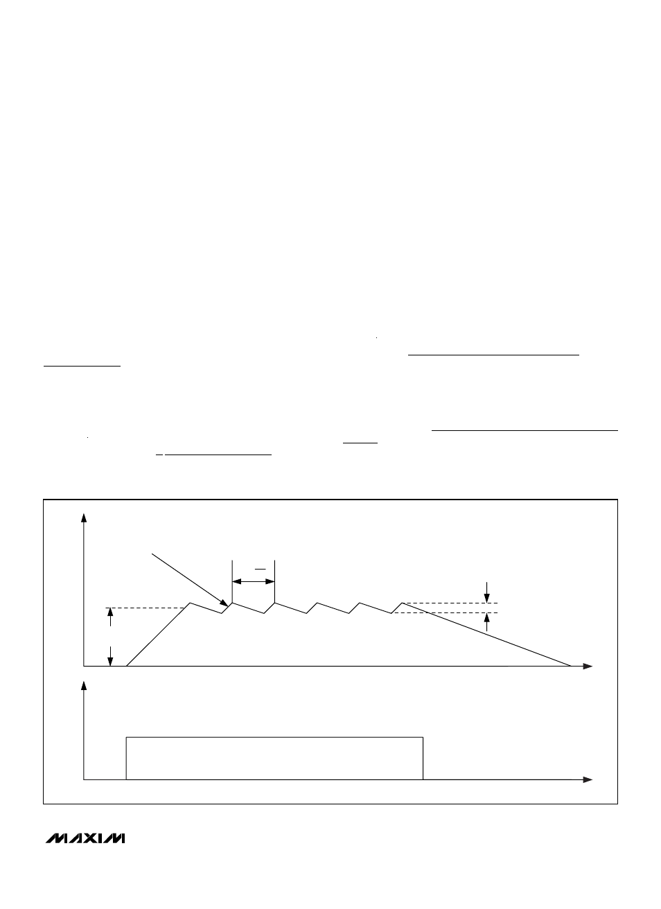
Current Regulator Operation
The MAX16819/MAX16820 regulate the LED output
current using an input comparator with hysteresis
(Figure 1). As the current through the inductor ramps
up and the voltage across the sense resistor reaches
the upper threshold, the voltage at DRV goes low, turn-
ing off the external MOSFET. The MOSFET turns on
again when the inductor current ramps down through
the freewheeling diode until the voltage across the
sense resistor equals the lower threshold. Use the fol-
lowing equation to determine the operating frequency:
where n = number of LEDs, V
LED
= forward voltage
drop of one LED, and ∆V = (V
SNSHI
- V
SNSLO
).
For proper component selection, please use the design
tool available at: http://www.maxim-ic.com/MAX16819-
20-Tool.
f
V
n V
n V
R
V
V L
SW
IN
LED
LED
SENSE
IN
=
− Ч
(
)
Ч Ч
Ч
Ч
Ч
∆
R
V
V
V
I
A
SENSE
SNSHI
SNSLO
LED
Ω
( )
=
+
(
)( )
( )
1
2
MAX16819/MAX16820
2MHz High-Brightness LED Drivers with
High-Side Current Sense and 5000:1 Dimming
_______________________________________________________________________________________
7
HYSTERETIC MODE
AVG. LED
CURRENT
1
f
SW
T
SW
=
I
LED
t
t
V
DIM
∆I
Figure 1. Current Regulator Operation