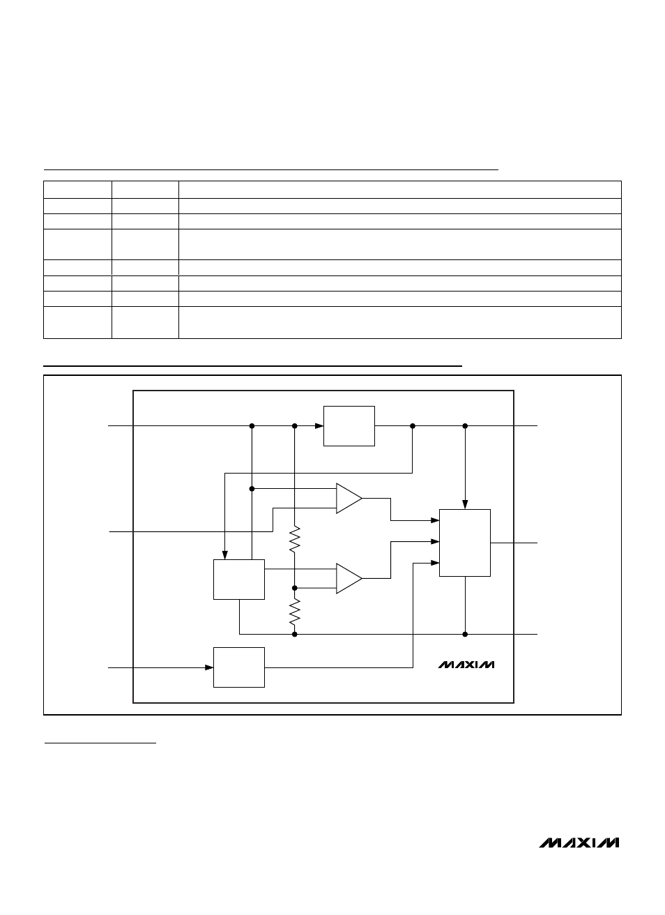
Pin description functional diagram, Detailed description – Rainbow Electronics MAX16820 User Manual
Page 6
MAX16819/MAX16820
2MHz High-Brightness LED Drivers with
High-Side Current Sense and 5000:1 Dimming
6
_______________________________________________________________________________________
MAX16819
MAX16820
REGULATOR
CS
COMPARATOR
UVLO
COMPARATOR
1.23V
BANDGAP
REF
GATE
DRIVER
DIM
BUFFER
V
CC
DRV
GND
+
-
-
+
CSN
IN
DIM
Pin Description
Functional Diagram
PIN
NAME
FUNCTION
1
IN
Positive Supply Voltage Input. Bypass with a 1µF or higher value capacitor to GND.
2
CSN
Current-Sense Input
3
DIM
Logic-Level Dimming Input. Drive DIM low to turn off the current regulator. Drive DIM high to enable
the current regulator.
4
GND
Ground
5
DRV
Gate Drive Output. Connect to the gate of an external n-channel MOSFET.
6
V
CC
Voltage Regulator Output. Connect a 1µF capacitor from V
CC
to GND.
EP
—
Exposed Paddle. Connect to a large-area ground plane for improved power dissipation. Do not use
as the only ground connection for the device.
Detailed Description
The MAX16819/MAX16820 are step-down, constant-
current, high-brightness LED (HB LED) drivers. These
devices operate from a 4.5V to 28V input voltage range
and provide up to 0.5A of source and 1A of sink drive
capability to the gate of an external MOSFET. A high-
side current-sense resistor sets the output current and
a dedicated PWM dimming input (DIM) allows for a
wide range of independent pulsed dimming.
The high-side current-sensing scheme and on-board
current-setting circuitry minimize the number of exter-
nal components while delivering LED current with a
±5% accuracy, using a 1% sense resistor. See the
Functional Diagram
.