4 0 dynamic performance – Rainbow Electronics ADC12441 User Manual
Page 13
4 0 Dynamic Performance
Many applications require the A D converter to digitize ac
signals but the standard dc integral and differential nonlin-
earity specifications will not accurately predict the A D con-
verter’s performance with ac input signals The important
specifications for ac applications reflect the converter’s abil-
ity to digitize ac signals without significant spectral errors
and without adding noise to the digitized signal Dynamic
characteristics such as signal-to-noise ratio (S N) signal-to-
noiseadistortion ratio (S (NaD)) effective bits full power
bandwidth aperture time and aperture jitter are quantitative
measures of the A D converter’s capability
An A D converter’s ac performance can be measured using
Fast Fourier Transform (FFT) methods A sinusoidal wave-
form is applied to the A D converter’s input and the trans-
form is then performed on the digitized waveform S (NaD)
and S N are calculated from the resulting FFT data and a
spectral plot may also be obtained Typical values for S N
are shown in the table of Electrical Characteristics and
spectral plots of S (NaD) are included in the typical per-
formance curves
The A D converter’s noise and distortion levels will change
with the frequency of the input signal with more distortion
and noise occurring at higher signal frequencies This can
be seen in the S (NaD) versus frequency curves These
curves will also give an indication of the full power band-
width (the frequency at which the S (NaD) or S N drops
3 dB)
Effective number of bits can also be useful in describing the
A D’s noise performance An ideal A D converter will have
some amount of quantization noise determined by its reso-
lution which will yield an optimum S N ratio given by the
following equation
S N e (6 02
c
n a 1 8)dB
where n is the A D’s resolution in bits
The effective bits of a real A D converter therefore can be
found by
n(effective) e
S N(dB)b1 8
6 02
As an example an ADC12441 with a
g
5V 10 kHz sine
wave input signal will typically have a S N of 78 dB which is
equivalent to 12 6 effective bits
Two sample hold specifications aperture time and aperture
jitter are included in the Dynamic Characteristics table
since the ADC12441 has the ability to track and hold the
analog input voltage Aperture time is the delay for the A D
to respond to the hold command In the case of the
ADC12441
the hold command is internally generated
When the Auto-Zero function is not being used the hold
command occurs at the end of the acquisition window or
seven clock periods after the rising edge of the WR The
delay between the internally generated hold command and
the time that the ADC12441 actually holds the input signal is
the aperture time For the ADC12441 this time is typically
100 ns Aperture jitter is the change in the aperture time
from sample to sample Aperture jitter is useful in determin-
ing the maximum slew rate of the input signal for a given
accuracy For example an ADC12441 with 100 ps of aper-
ture jitter operating with a 5V reference can have an effec-
tive gain variation of about 1 LSB with an input signal whose
slew rate is 12 V ms
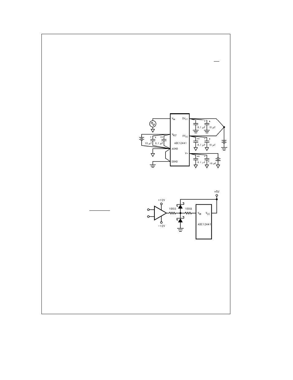
Power Supply Bypassing
TL H 11017 – 22
Tantalum
Ceramic
Protecting the Analog Inputs
TL H 11017 – 23
Note
External protection diodes should be able to withstand the op amp
current limit
13