Applications information, Functional diagrams, Digital control inputs – Rainbow Electronics MAX4912 User Manual
Page 8
MAX4910/MAX4911/MAX4912
Quad-SPDT, Clickless Audio Switches
with Negative Signal Handling
8
_______________________________________________________________________________________
Applications Information
Digital Control Inputs
The MAX4910/MAX4911/MAX4912 logic inputs accept
up to +5.5V, regardless of supply voltage. For example,
with a +3.3V supply, CB1, CB2, CB, and EN can be dri-
ven low to GND and high to +5.5V, allowing for mixed
logic levels in a system. Driving CB, CB1, CB2, and EN
rail-to-rail minimizes power consumption. For a +3.3V
supply voltage, the logic thresholds are +0.5V (low)
and +1.4V (high).
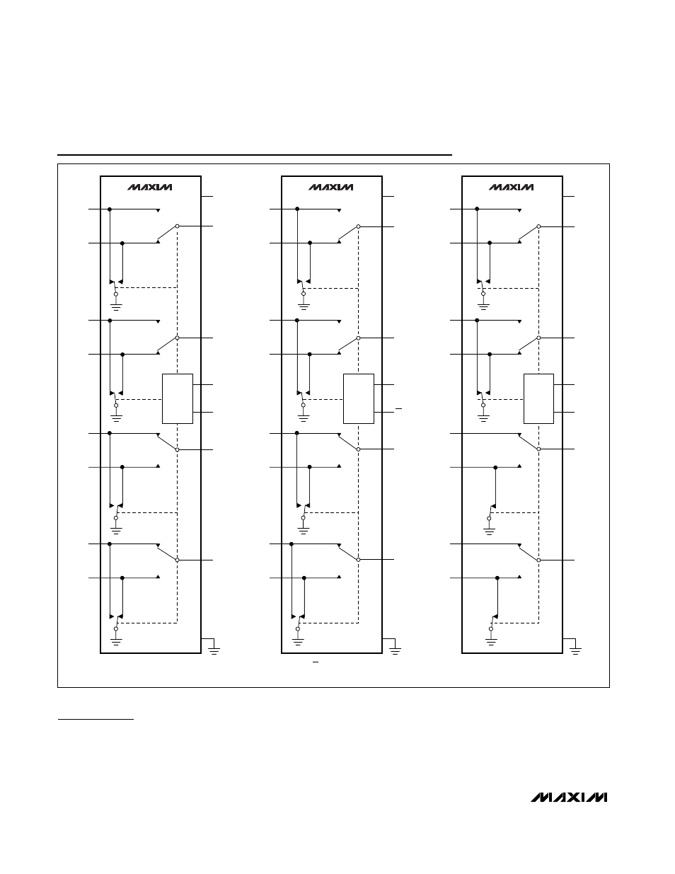
GND
MAX4910
V
CC
CB1
CB2
CONTROL
LOGIC
CB1 = 0, CB2 = 0.
NO3
NC3
COM3
NC2
NO2
COM2
NC4
NO4
COM4
NO1
NC1
COM1
GND
MAX4912
V
CC
CB1
CB2
CONTROL
LOGIC
CB1 = 0, CB2 = 0.
NO3
NC3
COM3
NC2
NO2
COM2
NC4
NO4
COM4
NO1
NC1
COM1
GND
MAX4911
V
CC
NO3
NC3
COM3
NC2
NO2
COM2
NC4
NO4
COM4
NO1
NC1
COM1
CB
CONTROL
LOGIC
EN
EN = 0, CB = 0.
DISCHARGE PATHS HAVE A 3.8k
Ω RESISTOR (NOT SHOWN).
Functional Diagrams