Detailed description, Pin description – Rainbow Electronics MAX4912 User Manual
Page 7
MAX4910/MAX4911/MAX4912
Quad-SPDT, Clickless Audio Switches
with Negative Signal Handling
_______________________________________________________________________________________
7
Detailed Description
The MAX4910/MAX4911/MAX4912 quad SPDT audio
switches are low on-resistance, low supply current,
high power-supply rejection ratio (PSRR) devices that
operate from a +1.8V to +5.5V single supply. These
devices feature a negative signal capability that allows
signals below GND to pass through without distortion
and break-before-make switching.
The MAX4910/MAX4912 have two digital control inputs
CB1 and CB2 where each bit controls a pair of switch-
es (see Table 1). The MAX4911 has an active-low
enable EN and a digital control bit CB. Driving EN low
takes the switches out of high impedance and CB con-
trols all four switches (see Table 2). The MAX4910/
MAX4911 have shunt resistors on all their NO and NC
terminals to suppress click-and-pop sounds that may
occur from switching to a precharged terminal. The
MAX4912 does not have click-and-pop suppression
resistors on NC2 and NC4 for applications that do not
require predischarge switching.
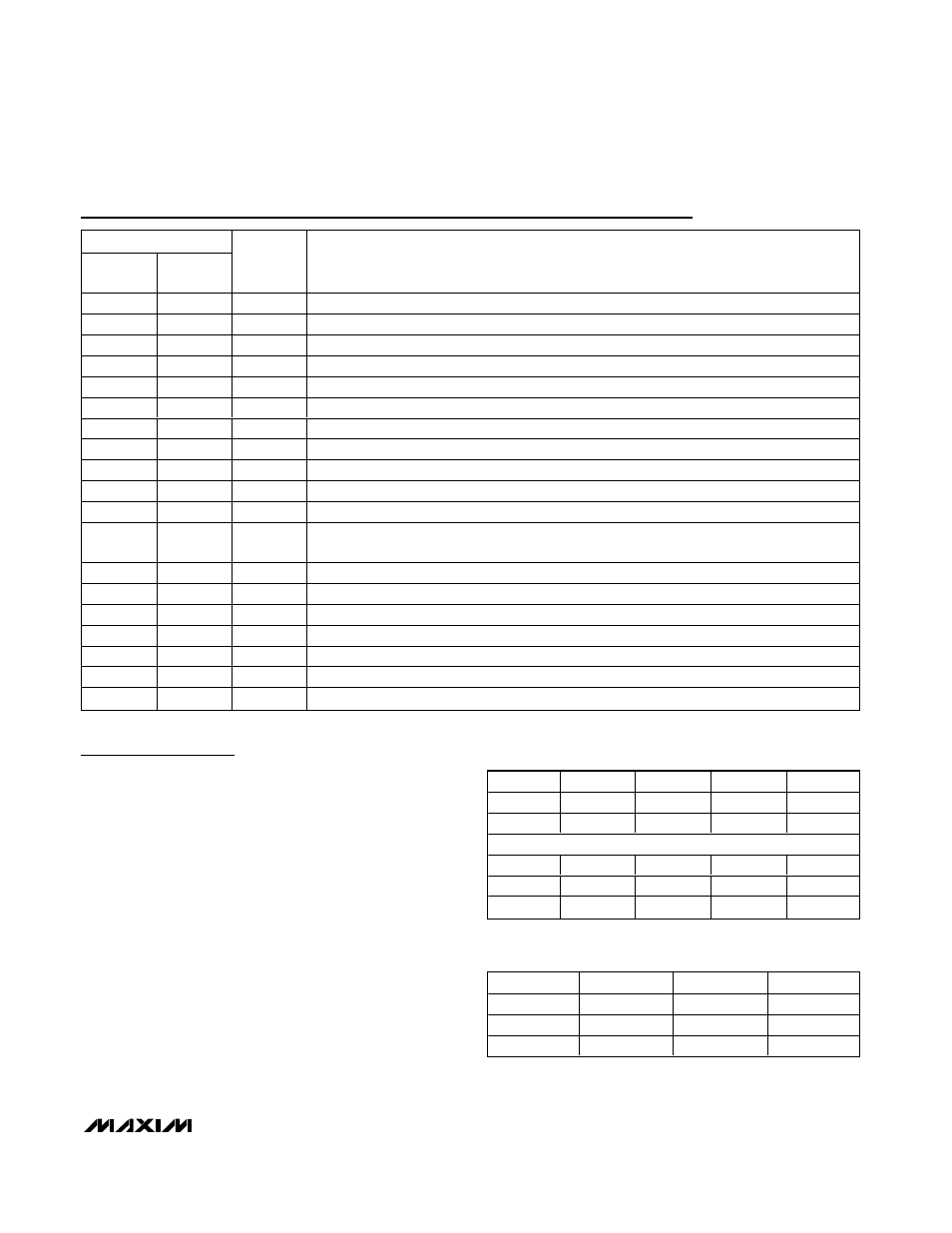
Pin Description
PIN
MAX4910/
MAX4912
MAX4911
NAME
FUNCTION
1
1
NC1
Analog Switch 1—Normally Closed Terminal
2
—
CB1
Digital Control Input for Analog Switch 1 and Analog Switch 3
—
2
CB
Digital Control Input for All Analog Switches
3
3
NO2
Analog Switch 2—Normally Open Terminal
4
4
COM2
Analog Switch 2—Common Terminal
5
5
NC2
Analog Switch 2—Normally Closed Terminal
6
6
GND
Ground
7
7
NO3
Analog Switch 3—Normally Open Terminal
8
8
COM3
Analog Switch 3—Common Terminal
9
9
NC3
Analog Switch 3—Normally Closed Terminal
10
—
CB2
Digital Control Input for Analog Switch 2 and Analog Switch 4.
—
10
EN
Enable Input. Driving EN high causes all switches to be high impedance. Pull EN low for
normal operation.
11
11
NO4
Analog Switch 4—Normally Open Terminal
12
12
COM4
Analog Switch 4—Common Terminal
13
13
NC4
Analog Switch 4—Normally Closed Terminal
14
14
V
CC
Positive Supply Voltage Input
15
15
NO1
Analog Switch 1—Normally Open Terminal
16
16
COM1
Analog Switch 1—Common Terminal
—
—
EP
Exposed Pad. Connect to Ground
Table 1. MAX4910/MAX4912 Truth Tables
CB1
NC1
NO1
NC3
NO3
0
On
Off
On
Off
1
Off
On
Off
On
CB2
NC2
NO2
NC4
NO4
0
On
Off
On
Off
1
Off
On
Off
On
Table 2. MAX4911 Truth Table
EN
CB
NC_
NO_
1
X
Off
Off
0
1
Off
On
0
0
On
Off
X = Don’t care.