Electrical characteristics – Rainbow Electronics ADC12038 User Manual
Page 5
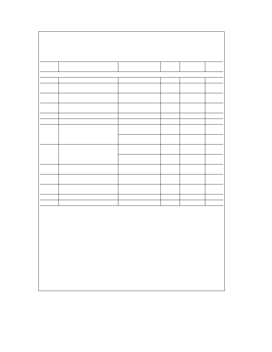
Electrical Characteristics
The following specifications apply for V
a
e
V
A
a
e
V
D
a
e a
5 0 V
DC
V
REF
a
e a
4 096 V
DC
V
REF
b
e
0 V
DC
12-bit a
sign conversion mode f
CK
e
f
SK
e
8 MHz for the ADC12H030 ADC12H032 ADC12H034 and ADC12H038 f
CK
e
f
SK
e
5 MHz for the ADC12030 ADC12032 ADC12034 and ADC12038 R
S
e
25X source impedance for V
REF
a
and V
REF
b
s
25X fully-differential input with fixed 2 048V common-mode voltage and 10(t
CK
) acquisition time unless otherwise specified
Boldface limits apply for T
A
e
T
J
e
T
MIN
to T
MAX
all other limits T
A
e
T
J
e
25 C (Notes 7 8 and 9)
Symbol
Parameter
Conditions
Typical
Limits
Units
(Note 10)
(Note 11)
(Limits)
REFERENCE INPUT ANALOG INPUTS AND MULTIPLEXER CHARACTERISTICS
C
REF
Reference Input Capacitance
85
pF
C
A D
A DIN1 and A DIN2 Analog Input
75
pF
Capacitance
A DIN1 and A DIN2 Analog Input
V
IN
e a
5 0V or
g
0 1
g
1 0
m
A (max)
Leakage Current
V
IN
e
0V
CH0 – CH7 and COM Input Voltage
GND b 0 05
V (min)
V
A
a
a
0 05
V (max)
C
CH
CH0 – CH7 and COM Input Capacitance
10
pF
C
MUXOUT
MUX Output Capacitance
20
pF
Off Channel Leakage (Note 16)
On Channel e 5V and
b
0 01
b
0 3
m
A (min)
CH0 – CH7 and COM Pins
Off Channel e 0V
On Channel e 0V and
0 01
0 3
m
A (max)
Off Channel e 5V
On Channel Leakage (Note 16)
On Channel e 5V and
0 01
0 3
m
A (max)
CH0 – CH7 and COM Pins
Off Channel e 0V
On Channel e 0V and
b
0 01
b
0 3
m
A (min)
Off Channel e 5V
MUXOUT1 and MUXOUT2
V
MUXOUT
e
5 0V or
0 01
0 3
m
A (max)
Leakage Current
V
MUXOUT
e
0V
R
ON
MUX On Resistance
V
IN
e
2 5V and
850
1150
X
(max)
V
MUXOUT
e
2 4V
R
ON
Matching Channel to Channel
V
IN
e
2 5V and
5
%
V
MUXOUT
e
2 4V
Channel to Channel Crosstalk
V
IN
e
5 V
PP
f
IN
e
40 kHz
b
72
dB
MUX Bandwidth
90
kHz
5