Detailed description, Pin description – Rainbow Electronics MAX9717 User Manual
Page 9
Detailed Description
The MAX9716/MAX9717 are 1.3W BTL speaker ampli-
fiers. Both devices feature a low-power shutdown
mode, and industry-leading click-and-pop suppression.
The MAX9717 features a headphone sense input that
disables the slave BTL amplifier to drive the headphone
as a single-ended load. These devices consist of high
output-current audio amps configured as BTL ampli-
fiers (see Functional Diagrams). The closed-loop gain
of the input op amp sets the single-ended gain of the
device. Two external gain resistors set the gain of the
MAX9716 and MAX9717A (see the Gain-Setting
Resistor section). The MAX9717B/C/D feature internally
set gains of 6dB, 9dB, and 12dB, respectively.
The output of the first amplifier serves as the input of the
second amplifier, which is configured as an inverting
unity-gain follower. This results in two outputs, identical in
amplitude, but 180° out-of-phase.
BIAS
The MAX9716/MAX9717 operate from a single 2.7V to
5.5V supply and feature an internally generated, common-
mode bias voltage of V
CC
/2 referenced to ground. BIAS
provides both click-and-pop suppression and sets the DC
bias level for the audio outputs. The MAX9716 can be
configured as a single-ended or differential input. For sin-
gle-ended input, connect the noninverting input IN+ to
BIAS externally. The MAX9717 BIAS is internally connect-
ed to the amplifier noninverting input IN+.
The MAX9717 can only be used with a single-ended
input. Always bypass BIAS to ground with a capacitor.
Choose the value of the bypass capacitor as described in
the BIAS Capacitor section. Do not connect external loads
to BIAS. Any load lowers the BIAS voltage, affecting the
overall performance of the device.
BTL
/SE Control Input
The MAX9717 features a headphone sense input,
BTL/SE, that enables headphone jack sensing to con-
trol the power amplifier output configuration. Driving
BTL/SE low enables the slave amplifier (OUT-). Driving
BTL/SE high disables the slave amplifier.
Shutdown Mode
The MAX9716/MAX9717 feature a low-power shutdown
mode that reduces quiescent current consumption to
10nA. Entering shutdown disables the bias circuitry,
forces the amplifier outputs to GND through an internal
20k
Ω resistor. Drive SHDN low to enter shutdown
mode; drive SHDN high for normal operation.
Click-and-Pop Suppression
The MAX9716/MAX9717 feature Maxim’s industry-leading
click-and-pop suppression circuitry. During startup, the
amplifier common-mode bias voltage ramps to the DC
bias. When entering shutdown, the amplifier outputs are
pulled to GND through an internal 20k
Ω resistor. This
scheme minimizes the energy present in the audio band.
MAX9716/MAX9717
Low-Cost, Mono, 1.4W BTL Audio Power
Amplifiers
_______________________________________________________________________________________
9
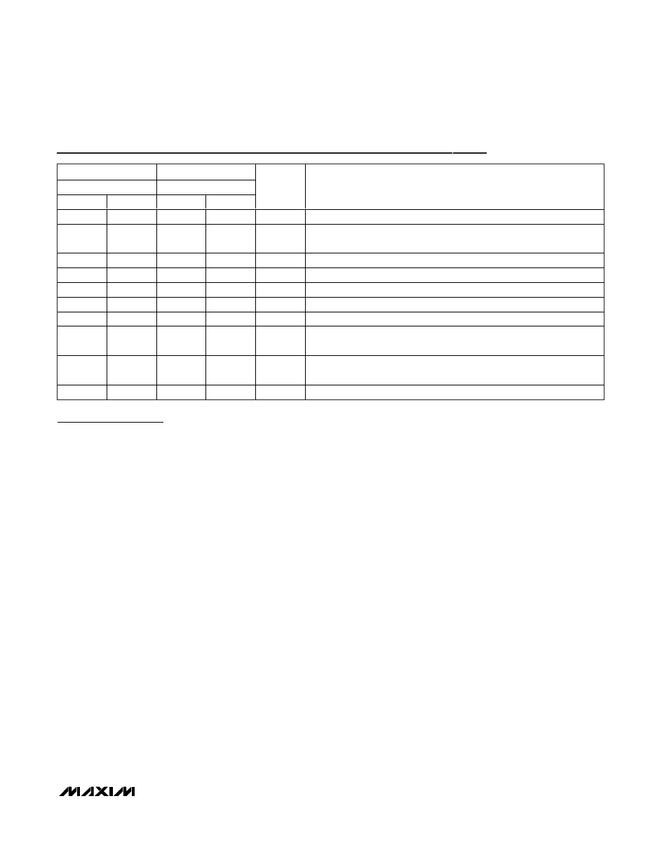
Pin Description
PIN
BUMP
TDFN/µMAX
UCSP
MAX9716
MAX9717
MAX9716
MAX9717
NAME
FUNCTION
1
1
C3
C3
SHDN
Active-Low Shutdown
2
2
C1
C1
BIAS
DC Bias Bypass Capacitor Connection. Bypass BIAS to ground with a
1µF capacitor.
3
—
A3
—
IN+
Noninverting Input
4
4
A1
A1
IN-
Inverting Input
5
5
A2
A2
OUT+
Bridge Amplifier Positive Output
6
6
B3
B3
V
CC
Power Supply. Bypass V
CC
with a 1µF capacitor to ground.
7
7
B1, B2
B1, B2
GND
Ground
8
8
C2
C2
OUT-
Bridge Amplifier Negative Output. OUT- becomes high-impedance
when BTL/SE is driven high.
—
3
—
A3
BTL/SE
BTL/Single-Ended Mode Input. Logic low sets the device in BTL mode.
Logic high sets the device in single-ended mode.
EP
EP
—
—
EP
Exposed Pad. Connect EP to GND.