Low-cost, mono, 1.4w btl audio power amplifiers, Applications information – Rainbow Electronics MAX9717 User Manual
Page 10
MAX9716/MAX9717
Applications Information
BTL Amplifier
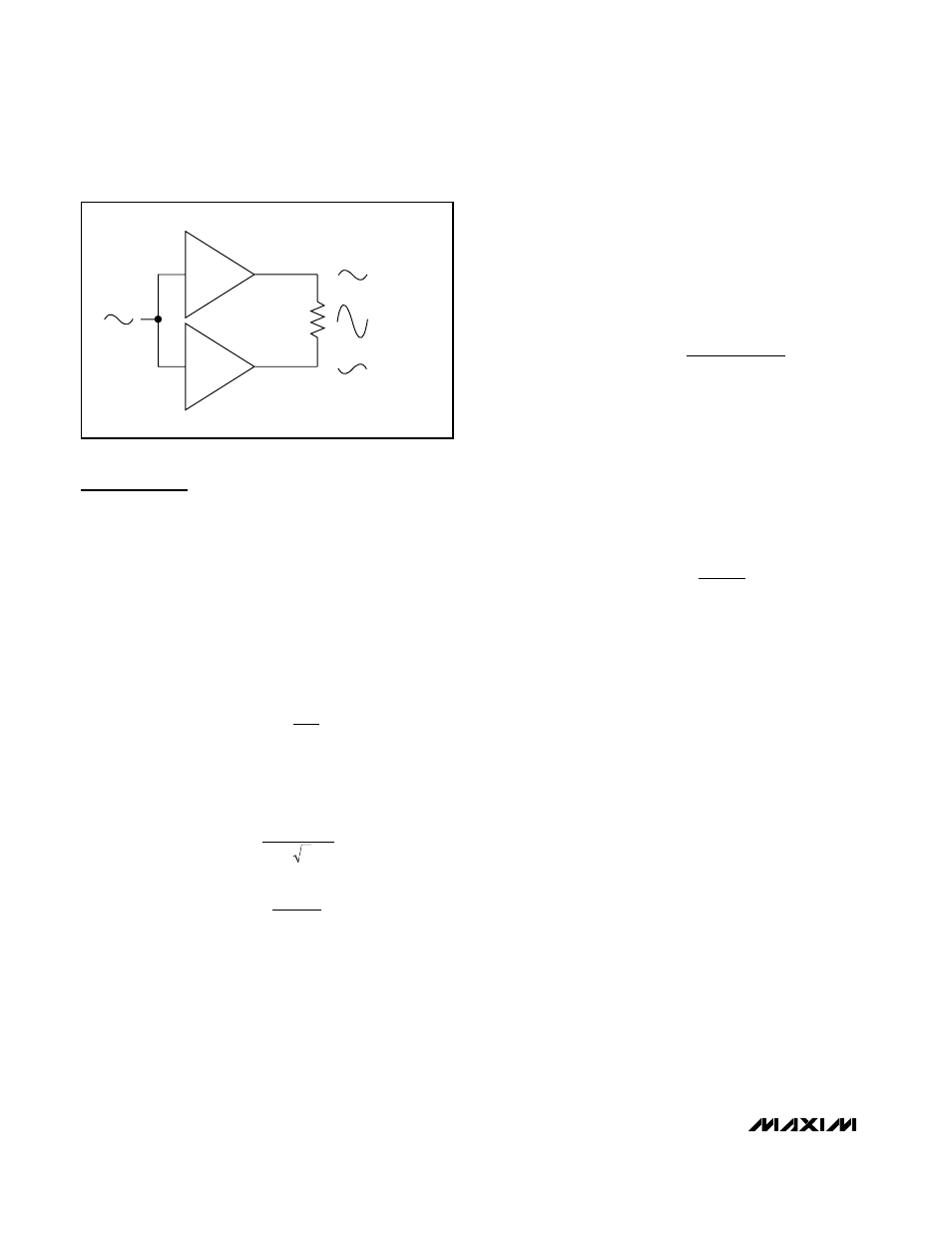
The MAX9716/MAX9717 are designed to drive a load
differentially, a configuration referred to as bridge-tied
load or BTL. The BTL configuration (Figure 1) offers
advantages over the single-ended configuration, where
one side of the load is connected to ground. Driving the
load differentially doubles the output voltage compared
to a single-ended amplifier under similar conditions.
Thus, the differential gain of the device is twice the
closed-loop gain of the input amplifier. The effective
gain is given by:
Substituting 2 x V
OUT(P-P)
for V
OUT(P-P)
into the following
equations yields four times the output power due to
doubling of the output voltage:
There is no net DC voltage across the load because the
differential outputs are each biased at midsupply. This
eliminates the need for DC-blocking capacitors
required for single-ended amplifiers. These capacitors
can be large and expensive, consume board space,
and degrade low-frequency performance.
Power Dissipation and Heat Sinking
Under normal operating conditions, the MAX9716/
MAX9717 dissipate a significant amount of power. The
maximum power dissipation for each package is given
in the Absolute Maximum Ratings section under
Continuous Power Dissipation or can be calculated by
the following equation:
where T
J(MAX)
is +150°C, T
A
is the ambient temperature,
and
θ
JA
is the reciprocal of the derating factor in °C/W as
specified in the Absolute Maximum Ratings section. For
example,
θ
JA
of the TDFN package is 41°C/W.
The increase in power delivered by the BTL configuration
directly results in an increase in internal power dissipation
over the single-ended configuration. The maximum power
dissipation for a given V
CC
and load is given by the
following equation:
If the power dissipation for a given application exceeds
the maximum allowed for a given package, reduce
power dissipation by increasing the ground plane heat-
sinking capability and the size of the traces to the device
(see the Layout and Grounding section). Other methods
for reducing power dissipation are to reduce V
CC
,
increase load impedance, decrease ambient tempera-
ture, reduce gain, or reduce input signal.
Thermal-overload protection limits total power dissipation
in the MAX9716/MAX9717. Thermal protection circuitry
disables the amplifier output stage when the junction
temperature exceeds +160°C. The amplifiers are
enabled once the junction temperature cools by 15°C. A
pulsing output under continuous thermal-overload condi-
tions results as the device heats and cools.
Fixed Gain
The MAX9717B, MAX9717C, and MAX9717D feature
internally fixed gains of 6dB, 9dB, and 12dB, respec-
tively (see the Selector Guide). Fixed gain simplifies
designs, reduces pin count, decreases required foot-
print size, and eliminates external gain-setting resistors.
Resistors R
IN
and R
F
shown in the MAX9717B/C/D
Typical Operating Circuit are used to achieve each
fixed gain.
P
V
R
DISS MAX
CC
L
(
)
=
2
2
2
π
P
T
T
DISSPKG MAX
J MAX
A
JA
(
)
(
)
=
−
θ
P
V
R
OUT
RMS
L
=
2
V
V
RMS
OUT P P
(
)
=
−
2 2
A
R
R
V
F
IN
=
×
2
Low-Cost, Mono, 1.4W BTL Audio Power
Amplifiers
10
______________________________________________________________________________________
+1
V
OUT(P-P)
2 x V
OUT(P-P)
V
OUT(P-P)
-1
Figure 1. Bridge-Tied Load Configuration