Low-cost, mono, 1.4w btl audio power amplifiers – Rainbow Electronics MAX9717 User Manual
Page 12
MAX9716/MAX9717
BIAS Capacitor
BIAS is the output of the internally-generated V
CC
/2 bias
voltage. The BIAS bypass capacitor, C
BIAS
, improves the
power-supply rejection ratio by reducing power supply
and other noise sources at the common-mode bias node.
C
BIAS
also generates the clickless/popless startup DC
bias waveform for the speaker amplifiers. Bypass BIAS
with a 1µF capacitor to GND. Larger C
BIAS
values
improve PSRR but slow down t
ON
time. Do not connect
external loads to BIAS.
Supply Bypassing
Proper power-supply bypassing ensures low-noise,
low-distortion performance. Connect a 1µF ceramic
capacitor from V
CC
to GND. Add additional bulk
capacitance as required by the application. Connect
the bypass capacitor as close to the device as possible.
Layout and Grounding
Proper PC board layout and grounding is essential for
optimizing performance. Use large traces for the
power-supply inputs and amplifier outputs to minimize
losses due to parasitic trace resistance. Large traces
also aid in moving heat away from the package. Proper
grounding improves audio performance and prevents
digital switching noise from coupling into the audio signal.
The MAX9716/MAX9717 TDFN and µMAX packages
feature exposed thermal pads on their undersides. This
pad lowers the thermal resistance of the package by
providing a direct-heat conduction path from the die to
the printed circuit board. Connect the exposed pad to
the ground plane using multiple vias, if required.
Low-Cost, Mono, 1.4W BTL Audio Power
Amplifiers
12
______________________________________________________________________________________
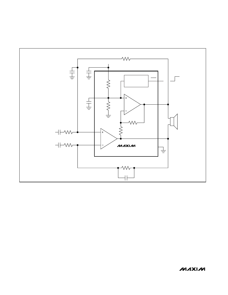
CLICKLESS/POPLESS
SHUTDOWN
CONTROL
BIAS
IN+
IN-
OUT+
OUT-
SHDN
GND
MAX9716
R
F
20k
Ω
R
F
20k
Ω
V
CC
R
IN
20k
Ω
C
IN
0.33
µF
AUDIO
INPUT
R
IN
20k
Ω
C
IN
0.33
µF
AUDIO
INPUT
C
BIAS
220pF
220pF
20k
Ω
20k
Ω
V
CC
VALUES SHOWN FOR 0dB GAIN.
OFF
ON
Figure 4. MAX9716 Differential Input