Pin description – Rainbow Electronics MAX9589 User Manual
Page 6
MAX9586–MAX9589
Single, Dual, Triple, and Quad Standard-Definition
Video Filter Amplifiers with AC-Coupled Input Buffers
6
_______________________________________________________________________________________
Pin Description
PIN
MAX9586
MAX9587
MAX9588
MAX9589
5 SOT23
6 TDFN
6 SOT23
6 µDFN
8 µMAX
8 µDFN
10 µMAX
12 TQFN
NAME
FUNCTION
1
3
—
—
—
—
—
—
SHDN
Active-Low Shutdown Input.
Connect to GND to shut down.
2
1
2
2
4
4
5
7
GND
Ground
3
2
—
—
—
—
—
—
IN
Video Input
—
—
3
1
1
1
1
3
INA
Video Input A
—
—
1
3
2
2
2
4
INB
Video Input B
—
—
—
—
3
3
3
5
INC
Video Input C
—
—
—
—
—
—
4
6
IND
Video Input D
4
6
—
—
—
—
—
—
OUT
Video Output
—
—
4
6
7
7
9
12
OUTA
Video Output A
—
—
6
4
6
6
8
11
OUTB
Video Output B
—
—
—
—
5
5
7
10
OUTC
Video Output C
—
—
—
—
—
—
6
9
OUTD
Video Output D
5
4
5
5
8
8
10
1
V
DD
Positive Power Supply. Bypass to
GND with a 0.1µF capacitor.
—
5
—
—
—
—
—
2, 8
N.C.
No Connection. Not internally
connected.
—
EP
—
—
—
—
—
EP
EP
Exposed Paddle. Connect EP to
GND. EP is also internally
connected to GND.
IN
SHDN
+3.3V
0.1µF
0.1µF
0.1µF
75Ω
OUT
CVBS
GND
V
DD
LPF
A
V
= 2V/V
MAX9586
CLAMP
VIDEO
SWITCH
LPF
A
V
= 2V/V
MAX9587
CLAMP
LPF
A
V
= 2V/V
BIAS
VIDEO
DECODER
3.3V
75Ω
INA
0.1µF
0.1µF
0.1µF
75Ω
OUTA
LUMA
GND
V
DD
VIDEO
DECODER
VIDEO
SWITCH
3.3V
75Ω
INB
0.1µF
0.1µF
75Ω
OUTB
CHROMA
75Ω
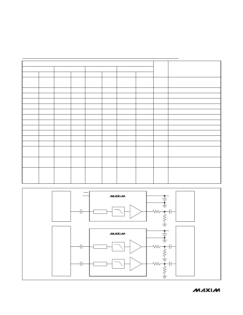
Figure 1. Typical Application Circuits for the MAX9586/MAX9587 (Anti-Alias Filter)