Electrical characteristics (continued) – Rainbow Electronics MAX6640 User Manual
Page 3
MAX6640
2-Channel Temperature Monitor with Dual
Automatic PWM Fan-Speed Controller
_______________________________________________________________________________________
3
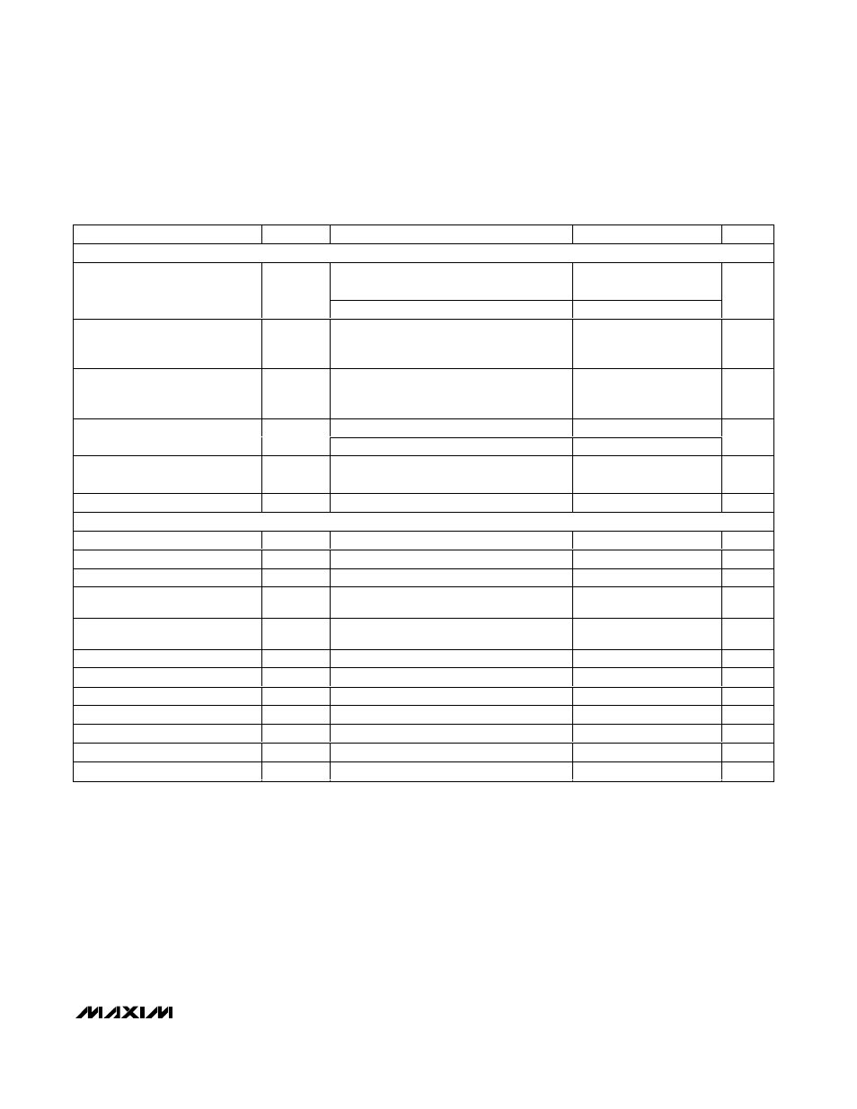
ELECTRICAL CHARACTERISTICS (continued)
(V
CC
= +3.0V to +5.5V, T
A
= 0°C to +125°C, unless otherwise noted. Typical values are at V
CC
= +3.3V, T
A
= +85°C.) (Note 1)
PARAMETER
SYMBOL
CONDITIONS
MIN
TYP
MAX
UNITS
DIGITAL INPUTS AND OUTPUTS
ALERT, FANFAIL, THERM, OT
SDA I
SINK
= 6mA
0.4
Output Low Voltage (Sink
Current) (OT, ALERT, FANFAIL,
THERM, SDA, PWM1, and PWM2)
V
OL
PWM1, PWM2, I
SINK
= 4mA
0.4
V
Output High Leakage Current
(OT, ALERT, FANFAIL, THERM,
SDA, PWM1, and PWM2)
I
OH
1
µA
Logic-Low Input Voltage (SDA,
SCL, THERM, TACH1, TACH2)
V
IL
0.8
V
V
CC
= 3.3V
2.1
Logic-High Input Voltage (SDA,
SCL, THERM, TACH1, TACH2)
V
IH
V
CC
= 5.5V
2.6
V
Input Leakage Current (SDA,
SCL, THERM, TACH1, TACH2)
V
IN
= V
CC
or GND
1
µA
Input Capacitance
C
IN
5
pF
SMBus TIMING (Note 2)
Serial Clock Frequency
f
SCL
(Note 3)
10
100
kHz
Clock Low Period
t
LOW
10% to 10%
4
µs
Clock High Period
t
HIGH
90% to 90%
4.7
µs
Bus Free Time Between Stop and
Start Condition
t
BUF
4.7
µs
SMBus Start Condition Setup
Time
t
SU:STA
90% of SMBCLK to 90% of SMBDATA
4.7
µs
Start Condition Hold Time
t
HD:STO
10% of SDA to 10% of SCL
4
µs
Stop Condition Setup Time
t
SU:STO
90% of SCL to 10% of SDA
4
µs
Data Setup Time
t
SU:DAT
10% of SDA to 10% of SCL
250
ns
Data Hold Time
t
HD:DAT
10% of SCL to 10% of SDA (Note 4)
300
ns
SMBus Fall Time
t
F
300
ns
SMBus Rise Time
t
R
1000
ns
SMBus Timeout
t
TIMEOUT
58
74
90
ms
Note 1: All parameters tested at a single temperature. Specifications are guaranteed by design.
Note 2: Timing specifications guaranteed by design.
Note 3: The serial interface resets when SCL is low for more than t
TIMEOUT
.
Note 4: A transition must internally provide at least a hold time to bridge the undefined region (300ns max) of SCL's falling edge.