Max6640, Table 4. fan duty-cycle rate-of-change, Table 5. fan rpm speed – Rainbow Electronics MAX6640 User Manual
Page 14
MAX6640
•
D[3:2]: Temperature Channel(s) for Fan Control.
Selects the temperature channel(s) that control the
PWM output when the MAX6640 is in automatic RPM
control mode (PWM mode bit is zero). If two chan-
nels are selected, the fan goes to the higher of the
two possible speeds. If neither channel is selected,
then the fan is in manual RPM mode and the speed
is forced to the value written to the target tach count
register 22h or 23h.
•
D[1:0]: RPM Range. Scales the tachometer counter
by setting the maximum (full-scale) value of the RPM
range to 2000, 4000, 8000, or 16,000. (Table 2
shows the internal clock frequency as a function of
the range.)
Fan 1 and 2 Configuration 2a (11h and 15h)
The following registers apply to the automatic RPM
control mode:
•
D[7:4]: Fan RPM (Tachometer) Step-Size A.
Selects the number of tachometer counts the target
value decreases for each temperature step increase
above the fan-start temperature. Value = n + 1 (1
through 16) where n is the value of D[7:4].
•
D[3:2]: Temperature Step Size. Selects the temper-
ature increment for fan control. For each temperature
step increase, the target tachometer count decreas-
es by the value selected by D[7:4] (Table 7).
•
D1: PWM Output Polarity. PWM output is low at
100% duty cycle when this bit is set to zero. PWM
output is high at 100% duty cycle when this bit is set
to 1.
•
D0: Minimum Speed. Selects the value of the mini-
mum fan speed (when temperature is below the fan-
start temperature in the automatic RPM control
mode). Set to zero for 0% fan drive. Set to 1 to deter-
mine the minimum fan speed by the tachometer
count value in registers 22h and 23h (fan maximum
TACH).
2-Channel Temperature Monitor with Dual
Automatic PWM Fan-Speed Controller
14
______________________________________________________________________________________
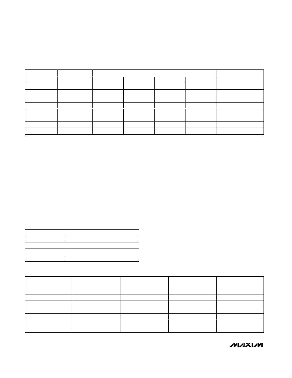
A C T U A L R A T E O F CH A N G E AT SPEC IF I C PW M FREQUENCIES
REGISTER 10h
OR 14h D[6:4]
NOMINAL RATE
OF CHANGE (s)
100Hz (s)
50Hz (s)
33.3Hz (s)
20Hz (s)
NOMINAL TIME FROM
33% TO 100% (s)
000
0
0
0
0
0
0
001
0.0625
0.06
0.06
0.06
0.05
5
010
0.125
0.13
0.12
0.12
0.15
10
011
0.25
0.25
0.26
0.24
0.25
20
100
0.5
0.5
0.5
0.51
0.5
40
101
1
1
1
0.99
1
80
110
2
2
2
1.98
2
160
111
4
4
4
3.96
4
320
Table 4. Fan Duty-Cycle Rate-of-Change
D[1:0]
FAN MAXIMUM RPM VALUE
00
2000
01
4000
10
8000
11
16,000
Table 5. Fan RPM Speed
MAXIMUM RPM VALUE
ACTUAL RPM
SELECTED NUMBER
OF PULSES PER
REVOLUTION
ACTUAL FAN PULSES
PER REVOLUTION
TACHOMETER COUNT
VALUE*
2000
1000
2
2
3Ch
4000
1000
2
2
78h
4000
3000
2
2
28h
4000
3000
2
4
14h
16,000
8000
4
4
3Ch
16,000
8000
4
2
78h
Table 6. RPM to Tachometer Count Relationship Examples
*Tachometer count value = ((internal clock frequency) x 60) / actual RPM) (selected number of pulses per revolution / actual fan pulses)