Max6640, Table 10. summary of fan-drive options, Table 11. remote-sensor transistor manufacturers – Rainbow Electronics MAX6640 User Manual
Page 18
MAX6640
Effect of Ideality Factor
The accuracy of the remote temperature measurements
depends on the ideality factor (n) of the remote diode
(actually a transistor). The MAX6640 is optimized for n
= 1.008, which is the typical value for the Intel®
Pentium® III and the AMD Athlon MP model 6. If a
sense transistor with a different ideality factor is used,
the output data is different. Fortunately, the difference
is predictable.
Assume a remote-diode sensor designed for a nominal
ideality factor n
NOMINAL
is used to measure the tem-
perature of a diode with a different ideality factor, n
1
.
The measured temperature T
M
can be corrected using:
where temperature is measured in Kelvin.
As mentioned above, the nominal ideality factor of the
MAX6640 is 1.008. As an example, assume the
MAX6640 is configured with a CPU that has an ideality
factor of 1.002. If the diode has no series resistance,
the measured data is related to the real temperature
as follows:
For a real temperature of +85°C (358.15K), the mea-
sured temperature is +82.91°C (356.02K), which is an
error of -2.13°C.
Effect of Series Resistance
Series resistance in a sense diode contributes addition-
al errors. For nominal diode currents of 10µA and
100µA, change in the measured voltage is:
∆V
M
= R
S
(100µA - 10µA) = 90µA x R
S
Since 1°C corresponds to 198.6µV, series resistance
contributes a temperature offset of:
Assume that the diode being measured has a series
resistance of 3Ω. The series resistance contributes an
offset of:
The effects of the ideality factor and series resistance
are additive. If the diode has an ideality factor of 1.002
and series resistance of 3Ω, the total offset can be cal-
culated by adding error due to series resistance with
error due to ideality factor:
1.36°C - 2.13°C = -0.77°C
for a diode temperature of +85°C.
In this example, the effect of the series resistance and
the ideality factor partially cancel each other.
For best accuracy, the discrete transistor should be a
small-signal device with its collector connected to GND
and base connected to DXN. Table 11 lists examples of
discrete transistors that are appropriate for use with the
MAX6640.
3
0 453
1 36
Ω ×
°
Ω
=
°
.
.
C
C
90
198 6
0 453
µ
Ω
µ
°
=
°
Ω
V
V
C
C
.
.
T
T
n
n
T
T
ACTUAL
M
NOMINAL
M
M
=
=
=
1
1 008
1 002
1 00599
.
.
( .
)
T
T
n
n
M
ACTUAL
NOMINAL
=
1
2-Channel Temperature Monitor with Dual
Automatic PWM Fan-Speed Controller
18
______________________________________________________________________________________
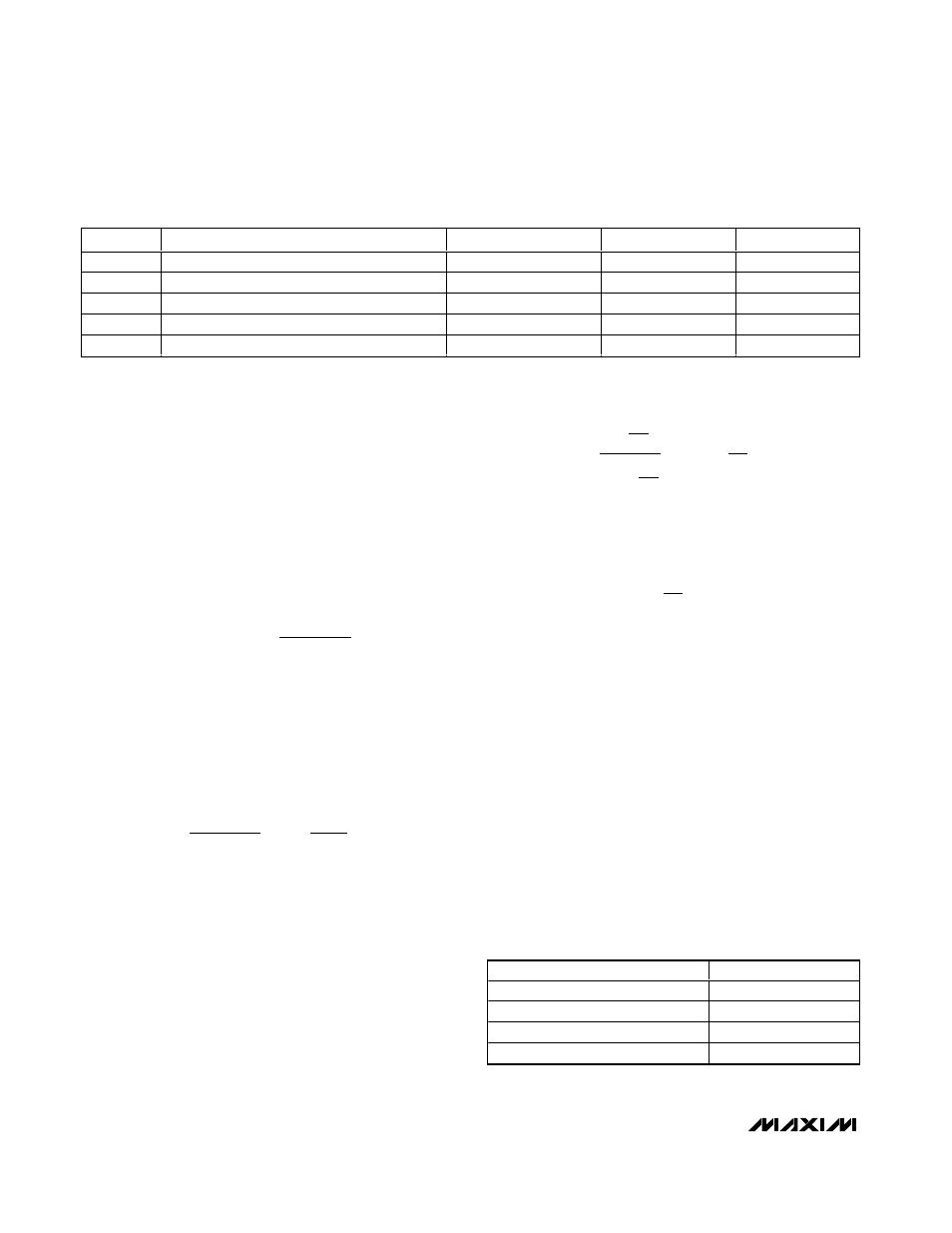
FIGURE
DESCRIPTION
PULSE STRETCHING
PWM FREQUENCY
PWM POLARITY
6
High-side PWM drive
Yes
Low
Negative
7
Low-side PWM drive
Yes
Low
Positive
8
High-side PWM drive with keep-alive supply
No
Low
Negative
9
High-side linear supply
No
High
Positive
10
4-wire fan with PWM speed-control input
No
High
Positive
Table 10. Summary of Fan-Drive Options
MANUFACTURER
MODEL NO.
Central Semiconductor (USA)
CMPT3906
Rohm Semiconductor (USA)
SST3906
Samsung (Korea)
KST3906-TF
Siemens (Germany)
SMBT3906
Table 11. Remote-Sensor Transistor
Manufacturers
Intel and Pentium are registered trademarks of Intel Corp.