Rainbow Electronics MAX6640 User Manual
Page 17
4-Wire Fans
Some fans have an additional, fourth terminal that
accepts a logic-level PWM speed-control signal as
shown in Figure 10. These fans require no external
power circuitry and combine the low noise of linear
drive with the high efficiency of PWM power-supply
drive. Higher PWM frequencies are recommended
when using 4-wire fans.
Quick-Start Guide for 8000RPM 4-Pole
(2 Pulses per Revolution) Fan in Automatic
RPM Mode Using the Circuit of Figure 7
1) Write 02h to register 11h to set the PWM output to
drive the n-channel MOSFET.
2) Write 4Bh to register 22h to set the minimum RPM
to 3200.
3) Write 5Eh to register 24h to set the pulses per revo-
lution to 2 and to set the maximum RPM speed to
8000RPM.
4) Write 19h to register 28h to set the fan-start temper-
ature to +25°C.
5) Write D2h to register 10h to start automatic
RPM mode.
Remote-Diode Considerations
Temperature accuracy depends upon having a good-
quality, diode-connected, small-signal transistor.
Accuracy has been experimentally verified for all the
devices listed in Table 11. The MAX6640 can also
directly measure the die temperature of CPUs and
other ICs with on-board temperature-sensing diodes.
The transistor must be a small-signal type with a rela-
tively high forward voltage. This ensures that the input
voltage is within the A/D input voltage range. The for-
ward voltage must be greater than 0.25V at 10µA at the
highest expected temperature. The forward voltage
must be less than 0.95V at 100µA at the lowest expect-
ed temperature. The base resistance has to be less
than 100Ω. Tight specification of forward-current gain
(+50 to +150, for example) indicates that the manufac-
turer has good process control and that the devices
have consistent characteristics.
MAX6640
2-Channel Temperature Monitor with Dual
Automatic PWM Fan-Speed Controller
______________________________________________________________________________________
17
V
CC
PWM1
4.7kΩ
4.7kΩ
TACH1
3V TO 5.5V
3V TO 5.5V
TACH
OUTPUT
V
FAN
(5V OR 12V)
Figure 10. 4-Wire Fan with PWM Speed-Control Input
V
CC
PWM1
4.7kΩ
4.7kΩ
TACH1
3V TO 5.5V
TACH
OUTPUT
V
FAN
(12V OR 5V)
5V
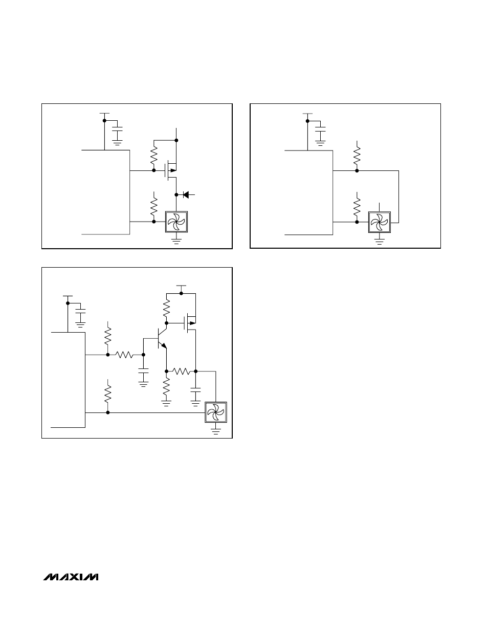
Figure 8. High-Side PWM Drive with “Keep-Alive” Supply
V
CC
PWM1
TACH1
4.7kΩ
3V TO 5V
4.7kΩ
100kΩ
91kΩ
33kΩ
100kΩ
3.3V
2N3904
2.2µF
10µF
TACH
OUTPUT
V
FAN
(5V OR 12V)
TACH OUTPUT
Figure 9. High-Side Linear Drive Circuit