Max6640, Applications information, Table 9. tachometer pulses per revolution – Rainbow Electronics MAX6640 User Manual
Page 16
MAX6640
Applications Information
Fan-Drive Circuits
A variety of fan-drive circuit configurations can be used
with the MAX6640 to control the fan’s speed. Four of
the most common are shown in Figures 6 through 10.
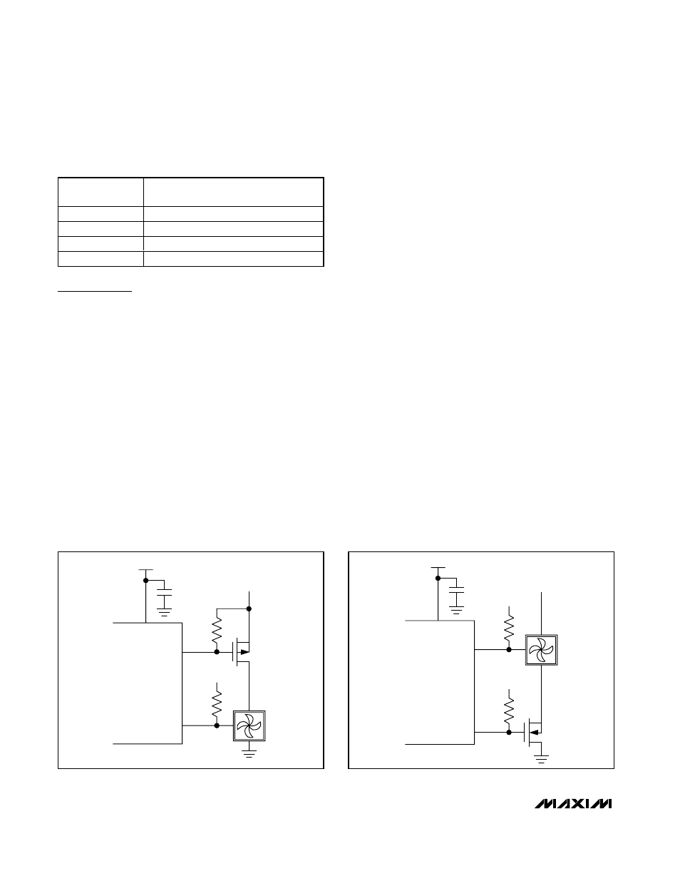
PWM Power-Supply Drive (High Side or Low Side)
The simplest way to control the speed of a 3-wire (sup-
ply, ground, and tachometer output) fan is to modulate
its power supply with a PWM signal. The PWM frequen-
cy is typically in the 20Hz to 40Hz range, with 33Hz
being a common value. If the frequency is too high, the
fan’s internal control circuitry does not have sufficient
time to turn on during a power-supply pulse. If the fre-
quency is too low, the power-supply modulation
becomes more easily audible.
The PWM can take place on the high side (Figure 6) or
the low side (Figure 7) of the fan’s power supply. In
either case, if the tachometer is used, it is usually nec-
essary to periodically stretch a PWM pulse so there is
enough time to count the tachometer pulse edges for
speed measurement. The MAX6640 allows this pulse
stretching to be enabled or disabled to match the
needs of the application.
Pulse stretching can sometimes be audible if the fan
responds quickly to changes in the drive voltage. If the
acoustic effects of pulse stretching are too noticeable,
the circuit in Figure 8 can be used to eliminate pulse
stretching while still allowing accurate tachometer feed-
back. The diode connects the fan to a low-voltage
power supply, which keeps the fan’s internal circuitry
powered even when the PWM drive is zero. Therefore,
the tachometer signal is always available and pulse
stretching can be turned off. Note that this approach
prevents the fan from turning completely off, so even
when the duty cycle is 0%, the fan may still spin.
Linear Fan Supply Drive
While many fans are compatible with PWM power-supply
drive, some are excessively noisy with this approach.
When this is the case, a good alternative is to control the
fan’s power-supply voltage with a variable DC power-
supply circuit. The circuit in Figure 10 accepts the PWM
signal as an input, filters the PWM, and converts it to a
DC voltage that then drives the fan. To minimize the size
of the filter capacitor, use the highest available PWM fre-
quency. Pulse stretching is not necessary when using a
linear fan supply. Note that this approach is not as effi-
cient as PWM drive, as the fan’s power-supply current
flows through the MOSFET, which can have an apprecia-
ble voltage across it. The total power is still less than
that of a fan running at full speed. Table 10 is a summa-
ry of fan-drive options.
2-Channel Temperature Monitor with Dual
Automatic PWM Fan-Speed Controller
16
______________________________________________________________________________________
D[7:6]
TACHOMETER PULSES PER
REVOLUTION
00
1
01
2
10
3
11
4
Table 9. Tachometer Pulses per
Revolution
V
CC
PWM1
4.7kΩ
4.7kΩ
TACH1
3V TO 5.5V
TACH
OUTPUT
V
FAN
(5V OR 12V)
Figure 6. High-Side PWM Drive Circuit
V
CC
TACH1
4.7kΩ
4.7kΩ
PWM1
3V TO 5.5V
3V TO 5.5V
TACH
OUTPUT
V
FAN
(5V OR 12V)
Figure 7. Low-Side Drive Circuit