Detailed description, Pin description – Rainbow Electronics MAX9656 User Manual
Page 7
MAX9655/MAX9656
Low-Power Video Switches
for Dual SCART Connectors
_______________________________________________________________________________________
7
Detailed Description
A MAX9655 or a MAX9656 can comprise the video por-
tion of a low-cost, dual SCART solution in set-top boxes
with a subset of the full SCART functions. The
MAX9655/MAX9656 select whether the CVBS, red,
green, and blue video signals from the encoder or the
VCR SCART are routed to the TV SCART. The
MAX9655/MAX9656 support the output of one CVBS
signal to the VCR SCART. In the MAX9655, the CVBS
signal from the encoder is routed to the VCR SCART.
In the MAX9656, the CVBS signal routed to the VCR
SCART can come from the encoder or TV SCART. In
the typical usage case, the VCR (or DVD recorder)
records a television program from the set-top box. In
such a case, the encoder would be the source of the
CVBS signal. Support for the TV SCART CVBS return
path is useful when a person wants to record on his
VCR (or more likely DVD recorder) a television program
received through the television’s antenna. The televi-
sion program is transmitted from the television to the
set-top box and then to the VCR.
Both the MAX9655 and MAX9656 have integrated
reconstruction filters so that when the encoder video
signals are routed to the TV SCART or the VCR SCART,
the steps and spikes left by the video digital-to-analog
converter (DAC) are smoothed away. Although the
incoming video signals from the VCR SCART are
assumed to be filtered already, the reconstruction filter
has wide enough bandwidth so that the video signals
from the VCR SCART are not degraded.
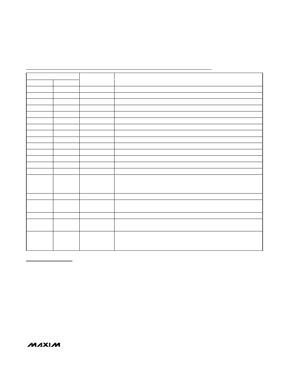
Pin Description
PIN
MAX9655
MAX9656
NAME
FUNCTION
1
2
ENC_B_IN
Encoder Blue Video Input. AC-couple the signal through a 0.1µF capacitor.
2
3
ENC_G_IN
Encoder Green Video Input. AC-couple the signal through a 0.1µF capacitor.
3
4
ENC_R_IN
Encoder Red Video Input. AC-couple the signal through a 0.1µF capacitor.
4
5
ENC_CVBS_IN
Encoder Composite Video Input. AC-couple the signal through a 0.1µF capacitor.
5
6
VCR_B_IN
VCR SCART Blue Video Input. AC-couple the signal through a 0.1µF capacitor.
6
7
VCR_G_IN
VCR SCART Green Video Input. AC-couple the signal through a 0.1µF capacitor.
7
8
VCR_R_IN
VCR SCART Red Video Input. AC-couple the signal through a 0.1µF capacitor.
8
9
VCR_CVBS_IN
V C R S C ART C om p osi te V i d eo Inp ut. AC - coup l e the si g nal thr oug h a 0.1µF cap aci tor .
9
11
GND
Ground
10
13
VCR_CVBS_OUT
VCR SCART Composite Video Output. The sync tip is biased at 0.3V.
11
14
TV_CVBS_OUT
TV SCART Composite Video Output. The sync tip is biased at 0.3V.
12
15
TV_R_OUT
TV SCART Red Video Output. The sync tip is biased at 0.3V.
13
16
TV_G_OUT
TV SCART Green Video Output. The sync tip is biased at 0.3V.
14
17
TV_B_OUT
TV SCART Blue Video Output. The sync tip is biased at 0.3V.
15
18
TV_SEL
TV SCART Output Selection. Connect to GND to route the encoder video signals
to the TV SCART outputs. Connect to V
DD
to route the VCR SCART video signals
to the TV SCART outputs.
16
19
V
DD
Positive Power Supply. Bypass with 0.1µF ceramic capacitors to GND.
—
1
TV_CVBS_IN
Television SCART Composite Video Input. AC-couple the signal through a 0.1µF
capacitor.
—
10
N.C.
No Connection. Not internally connected.
—
12
SHDN
Active-Low Shutdown Logic Input. Connect to GND to place device in shutdown.
Connect to V
DD
for normal operation.
—
20
VCR_SEL
VCR SCART Output Selection. Connect to GND to route ENC_CVBS_IN to the
VCR SCART CVBS output. Connect to V
DD
to route TV_CVBS_IN to the VCR
SCART CVBS output.