Abridged data sheet – Rainbow Electronics MAX66040 User Manual
Page 8
MAX66040
ISO/IEC 14443 Block
Transmission Protocol
Before the master can send a data packet to access the
memory, the MAX66040 must be in the ACTIVE state.
The protocol to put the MAX66040 into the ACTIVE state
is explained in the
Network Function Commands
sec-
tion. While in the ACTIVE state, the communication
between master and MAX66040 follows the block trans-
mission protocol as specified in Section 7 of ISO/IEC
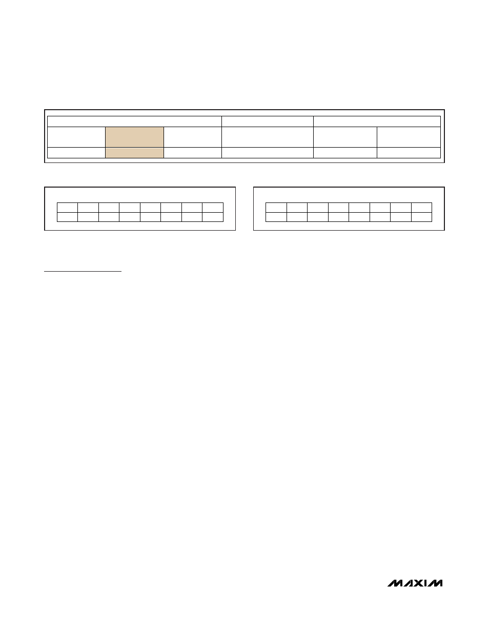
14443-4. Such a block (Figure 11) consists of three
parts: the prologue field, the information field, and the
epilogue field. The prologue can contain up to 3 bytes,
called the protocol control byte (PCB), card identifier
(CID), and the node address (NAD). Epilogue is another
name for the 16-bit CRC that precedes the EOF. The
information field is the general location for data.
Block Types
The standard defines three types of blocks: I-block,
R-block, and S-block. Figures 12, 13, and 14 show the
applicable PCB bit assignments.
The I-block is the main tool to access the memory and
to run the SHA-1 engine. For I-blocks, bit 2 must be 1
and bit 6, bit 7, and bit 8 must be 0. Bit 5, marked as
CH, is used to indicate chaining, a function that is not
used or supported by the MAX66040. Therefore, bit 5
must always be 0. Bit 4, marked as CID, is used by the
master to indicate whether the prologue field contains a
CID byte. The MAX66040 processes blocks with and
without CID as defined in the standard. The master
must include the CID byte if bit 4 is 1. Bit 3, marked as
NAD, is used to indicate whether the prologue field
contains an NAD byte, a feature not supported by the
MAX66040. Therefore, bit 3 must always be 0. Bit 1,
marked as #, is the block number field. The block num-
ber is used to ensure that the response received relates
to the request sent. This function is important in the
error handling, which is illustrated in Annex B of
ISO/IEC 14443-4. The rules that govern the numbering
and handling of blocks are found in sections 7.5.3 and
7.5.4 of ISO/IEC 14443-4. The MAX66040 ignores
I-blocks that have bit 5 or bit 3 set to 1.
For R-blocks, the states of bit 2, bit 3, and bit 6, bit 7,
and bit 8 are fixed and must be transmitted as shown in
Figure 13. The function of bit 1 (block number) and bit 4
(CID indicator) is the same as for I-blocks. Bit 5,
marked as AN, is used to acknowledge (if transmitted
as 0) or not to acknowledge (if transmitted as 1) the
reception of the last frame for recovery from certain
error conditions. The MAX66040 fully supports the func-
tion of the R-block as defined in the standard. For
details and the applicable rules, refer to Sections 7.5.3
and 7.5.4 and Annex B of ISO/IEC 14443-4.
ISO/IEC 14443 Type B-Compliant
Secure Memory
10
______________________________________________________________________________________
ABRIDGED DATA SHEET
PROLOGUE FIELD
INFORMATION FIELD
EPILOGUE FIELD
PCB
CID NAD
(DATA)
CRC
(LSB)
CRC
(MSB)
1 BYTE
1 BYTE
1 BYTE
0 OR MORE BYTES
1 BYTE
1 BYTE
Figure 11. ISO/IEC 14443-4 Type B Block Format
BIT 8
BIT 7
BIT 6
BIT 5
BIT 4
BIT 3
BIT 2
BIT 1
MSB
LSB
0
0
0
CH
CID
NAD
1
#
Figure 12. Bit Assignments for I-Block PCB
BIT 8
BIT 7
BIT 6
BIT 5
BIT 4
BIT 3
BIT 2
BIT 1
MSB
LSB
1
0
1
AN
CID
0
1
#
Figure 13. Bit Assignments for R-Block PCB