Abridged data sheet, Table 16. slot numbering – Rainbow Electronics MAX66040 User Manual
Page 18
number, R, in the range of 1 to N. A slave that happens
to choose R = 1 responds to the REQB/WUPB request.
The larger N is the lower the probability of colliding
response frames; however, if N is 16 and there is only a
single slave in the field, it can take up to 15 SLOT-
MARKER commands to get a response. The method to
identify all slaves in the field relying solely on the ran-
dom number R and the REQB/WUPB command is
called the “probabilistic approach.” For mode informa-
tion about the anticollision process see the
Anticollision
Examples
section.
SLOT-MARKER Command
Instead of relying on the fact that a participating slave
chooses a new random number for every REQB/WUPB
command, in the “time-slot approach” the master calls
the slaves by their random number R using the SLOT-
MARKER command. Before this can be done, the mas-
ter must have issued the REQB/WUPB command with a
number of slots (N) value greater than 1. The master
can send up to (N - 1) SLOT-MARKER commands.
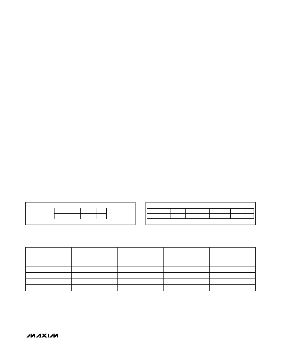
Figure 20 shows the format of the SLOT-MARKER
request frame. The AFI field is not needed since the
slaves have already been preselected through the pre-
ceding REQB/WUPB request. The response to the
SLOT-MARKER command is called ATQB. See the
ATQB Response
section for details.
The bits marked as “nnnn” specify the slot number as
defined in the Table 16. Any sequence of the allowable
slot numbers is permitted.
ATQB Response
The response for both the REQB/WUPB and the SLOT-
MARKER command is called ATQB, which stands for
“answer to request, Type B.” Figure 21 shows the for-
mat of the ATQB response. The PUPI field (pseudo-
unique identifier) is used by the master to address a
slave for transitioning to the ACTIVE or HALT state. The
data reported as PUPI is the least significant 4 bytes of
the 64-bit UID. The application data field reports user-
defined data that is relevant for distinguishing otherwise
equal slaves in the RF field. Application data is the first
4 bytes of memory block 10h. By default, the applica-
tion data field is factory programmed to reflect the most
significant 4 bytes of the 64-bit UID. This allows the
master to obtain the full 64-bit UID in the first response
from the slave. However, since this field is not factory
locked, it may be written to any value.
The protocol info field provides the master with admin-
istrative information, such as data rate, frame size,
ISO/IEC 14443-4 compliance, frame waiting time, and
whether the slave supports CID and NAD in the
ISO/IEC 14443-4 block transmission protocol. Figure 22
MAX66040
ISO/IEC 14443 Type B-Compliant
Secure Memory
______________________________________________________________________________________
27
COMMAND
SOF
CRC
EOF
nnnn0101b
(2 BYTES)
Figure 20. SLOT-MARKER Request Frame
INDICATOR
SOF
CRC
EOF
50h
APPLICATION DATA
(4 BYTES)
(2 BYTES)
PROTOCOL INFO
(3 BYTES)
PUPI
(4 BYTES)
Figure 21. ATQB Response Frame
BIT 8
BIT 7
BIT 6
BIT 5
SLOT NUMBER
0 0 0 1 2
0 0 1 0 3
0 0 1 1 4
… … … … …
1 1 1 0 15
1 1 1 1 16
Table 16. Slot Numbering
ABRIDGED DATA SHEET