Connecting to 3-wire phoenix terminal connectors, Installation and setup – Cobalt Digital COMPASS 9391 3G_HD_SD-SDI Timecode Burn-In Inserter User Manual
Page 23
9391-TCB-OM (V1.3)
9391-TCB PRODUCT MANUAL
2-5
Installation and Setup
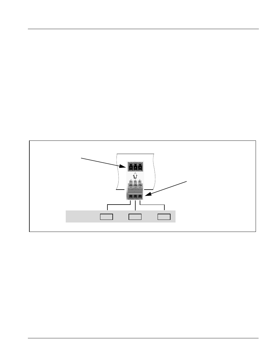
Connecting To 3-Wire Phoenix Terminal Connectors
Connecting To 3-Wire Phoenix Terminal Connectors
Figure 2-2 shows connections to the card 3-wire Phoenix™ terminal block
connectors. These connectors are used for card RS-485 LTC I/O connections.
These terminal blocks use a removable screw terminal binding post block
which allows easier access to the screw terminals.
Note:
It is preferable to wire connections to Phoenix plugs oriented as shown in
Figure 2-2
rather than assessing polarity on rear module connectors. Note
that the orientation of rear module connectors is not necessarily consistent
within a rear module, or between different rear modules. If wiring is first con-
nected to Phoenix plug oriented as shown here, the electrical orientation will
be correct regardless of rear module connector orientation.
Note:
An RS-485 input received by the card must have the customary zero-crossing
associated with RS-485. If the LTC source is offset above or below ground (0
V), the sources must be capacitively coupled or passed through an analog
audio DA that can restore zero-crossing.
Figure 2-2 3-Wire Phoenix Terminal Connections
A (-)
B (+)
G
RS-485
Removable Phoenix plug view oriented
with top (screw terminals) up
Note: RS-485 communication will not work if
any of the connections are reversed from
that shown here.
Rear module
PCB connector
RS-485 LTC Port Connections