Jumper locations, Leds – Cobalt Digital COMPASS 9232 Utility Analog Video Distribution Amplifier User Manual
Page 15
9232 Owner’s Manual (V 1.1)
15
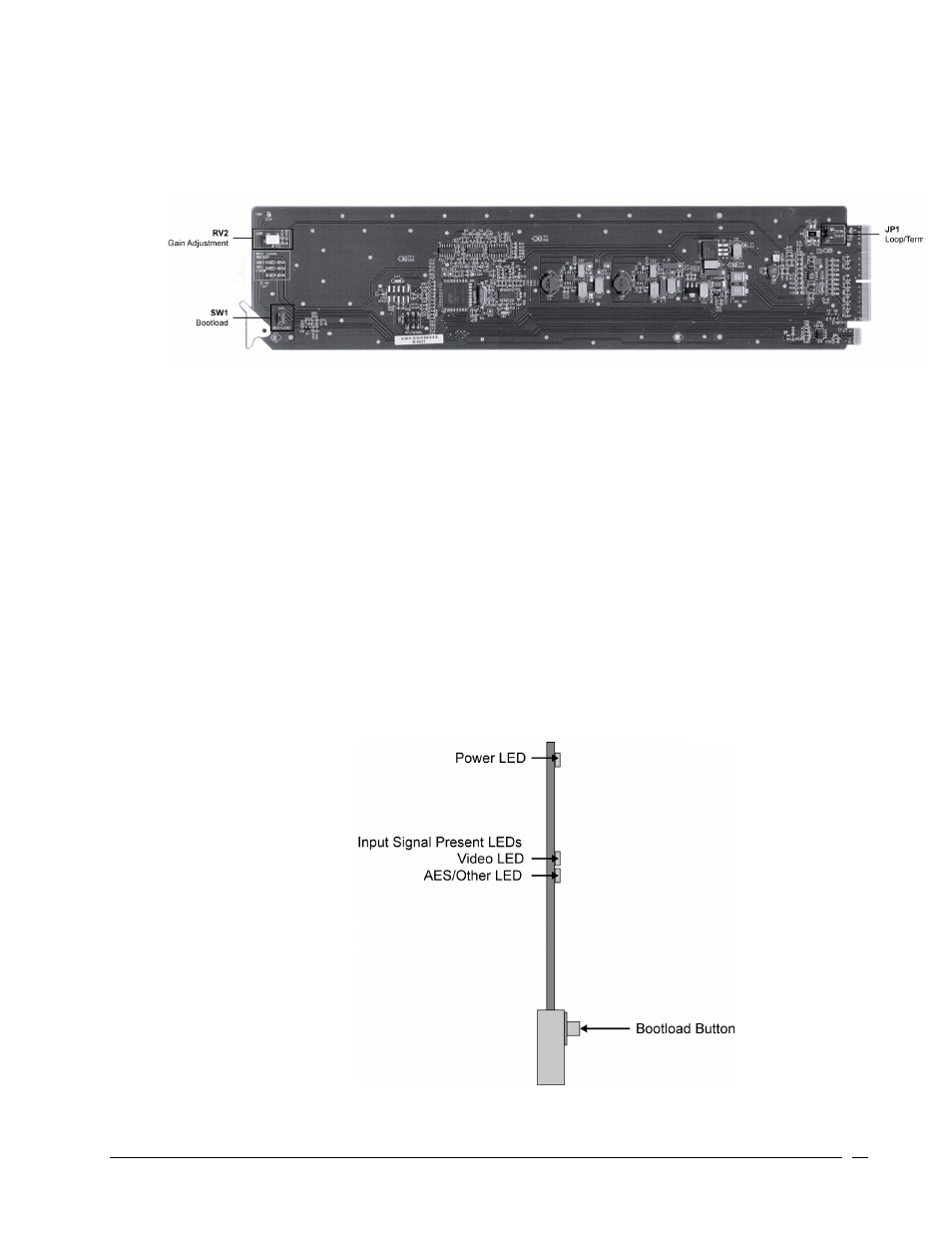
Jumper Locations
The following sections describe the jumpers on the 9232.
Figure 6. Jumper Locations
JP1 — Local Termination Jumper
The position of
JP2
selects an optional 75ohm termination on the input of the 9232 card.
Select one of the following options:
•
TERM — Install the jumper in this position to terminate the input signal on this
card. This is the default setting.
•
LOOP — Install the jumper in this position to leave the input unterminated. For
example, configure this setting if you wish to loop the signal to another device.
RV2 — Gain Adjustment
The rotation of
RV2
adjusts the Gain level of the 9232 and provides a gain range of +/- 3dB.
LEDs
The following sections describe the 9232 LEDs. Refer to Figure 8 for LED locations.
- COMPASS 9275 HD_SD-SDI Analog Audio De-Embedder (46 pages)
- COMPASS 9031 HD_SD 12-bit Analog to Digital Converter (22 pages)
- COMPASS 9061 Up_Down_Cross Converter (118 pages)
- COMPASS 9362 HD_SD-SDI Test Signal Generator (54 pages)
- COMPASS 9374-EMDE Quad-Stream SDI – AES – MADI Embedder_De-embedder (70 pages)
- BLUE BOX GROUP HDMI-To-SDI HDMI-to-3G_HD_SD-SDI (2 pages)
- COMPASS 9011 Standard Definition D_A 10-bit SDI to Analog Composite, Y_C and Component (22 pages)
- COMPASS 9083 HD_SD Frame Sync (106 pages)
- BLUE BOX GROUP Fiber-To-Coax 3G_HD_SD-SDI _ DVB _ ASI Fiber Optic Transport Receiver (2 pages)
- COMPASS 9003 Dual 3G_HD_SD Reclocking Distribution Amplifier (20 pages)
- COMPASS 9002 3G_HD_SD Distribution Amplifier (Non-Reclocking) (18 pages)
- COMPASS 9005 Triple 3G_HD_SD Reclocking Distribution Amplifier (20 pages)
- COMPASS 9223 Dual-Channel 3G_HD_SD MPEG-4 Encoder (100 pages)
- COMPASS 9229-QS Quad-Split Video Processor (63 pages)
- COMPASS 9305 Embedded Audio Delay Processor (64 pages)
- FUSION 3G 9931-EMDE 3G_HD_SD-SDI Embedder_De-Embedder (124 pages)
- COMPASS 9392 3G_HD_SD-SDI Dual-Channel Timecode Burn-In Inserter (50 pages)
- COMPASS 9223-SA Dual-Channel 3G_HD_SD MPEG-4 Encoder Unit (106 pages)
- BLUE BOX GROUP Coax-To-Fiber 3G_HD_SD-SDI _ DVB _ ASI _ MADI Fiber Optic Transport Transmitter (2 pages)
- BLUE BOX GROUP Dual Fiber-To-Coax 3G_HD_SD-SDI _ DVB _ ASI _ MADI Fiber Optic Dual Transport Receiver (2 pages)
- COMPASS 9216-OE-DM AES_EBU Fiber Audio De-Embedder (53 pages)
- COMPASS 9822 Downconverter (86 pages)
- COMPASS 9004 Dual 3G_HD_SD Distribution Amplifier (Non-Reclocking) (20 pages)
- COMPASS 9121 3G_HD_SD-SDI_ASI Redundancy Switch (30 pages)
- FUSION 3G 9921-FS 3G_HD_SD Frame Sync (124 pages)
- COMPASS 9257 1x9 MADI Audio Distribution Amplifier (19 pages)
- COMPASS 9212-EO 3G_HD_SD-SDI Fiber Transmitter (45 pages)
- COMPASS 9252 AES Audio Distribution Amplifier, 110 Ohms (16 pages)
- COMPASS 9262 Stereo AES to Analog Audio D_A Converter (18 pages)
- COMPASS 9082 HD_SD Frame Sync (56 pages)
- COMPASS 9033 Input Processing Analog to Digital Video (90 pages)
- COMPASS 9062 Up_Down_Cross Converter (92 pages)
- BLUE BOX GROUP Coax_Fiber Transceiver 3G_HD_SD-SDI _ DVB _ ASI _ MADI Fiber Optic Transport Transceiver (2 pages)
- SPOTCHECK Transport Stream Compliance Monitor (5 pages)
- COMPASS 9241 Analog Audio Distribution Amplifier (19 pages)
- BLUE BOX GROUP Fiber Regenerator 3G_HD_SD-SDI _ DVB _ ASI _ MADI Fiber Optic Transport Regenerator (2 pages)
- COMPASS 9284 3G_HD_SD-SDI 8X4 Video Routing Switch (58 pages)
- COMPASS 9032 HD_SD 12-bit Analog to Digital Converter (26 pages)
- COMPASS 9220 Bidirectional ASI_MPTS Gateway (61 pages)
- COMPASS 9001 3G_HD_SD Reclocking Distribution Amplifier (20 pages)
- BLUE BOX GROUP SDI-To-HDMI 3G_HD_SD-SDI-to-HDMI (2 pages)
- COMPASS 9071 HD_SD-SDI AFD Code Inserter (48 pages)
- COMPASS 9242 Analog Audio Distribution Amplifier with Remote Gain Control (36 pages)
- COMPASS 9034 Input Processing Analog to Digital Video (98 pages)