Moog Music MF-104Z Analog Delay User Manual
Page 19
19
delay chips, expander, and lowpass output filters. The output of this
function appears directly at the
LOOP OUT
jack. Its nominal level at
this jack is 0 dBm (about 0.8 volts
rms) when the INPUT LEVEL light is
red-yellow.
When the INPUT LEVEL light is
yellow or red, several points in the
circuit begin to saturate gradually,
thereby limiting the maximum
signal level and introducing some low-order distortion. This is a
normal component of the sound of analog gear. It actually enhances
the sound quality over what you would have if the MF-104Z
produced no distortion whatsoever (i.e., if it were `technically
perfect')
The delay time is varied by changing the frequency of the
oscillator that clocks, or advances, the bucket brigade chips. This
oscillator is a VCO (Voltage Controlled Oscillator) that operates over
the frequency range of 10 kHz to 200 kHz. Unlike conventional audio
VCO's or LFO's, increasing the control voltage of the clock oscillator
decreases the clock's frequency in such a way that the time delay
increases in exact proportion to the
control voltage change. (The clock
VCO's signal itself is not accessible
to the user.)
Except for the DRIVE and
LOOP GAIN
potentiometers, none
of the panel controls actually
handles the audio signals. This
reduces the probability that dirty
or worn potentiometers will
contribute to audio noise.
Technical specifications of all input and output jacks are given at
the end of this booklet.
POWER:
The MF-104Z works satisfactorily on +9 to +15 volts DC and uses
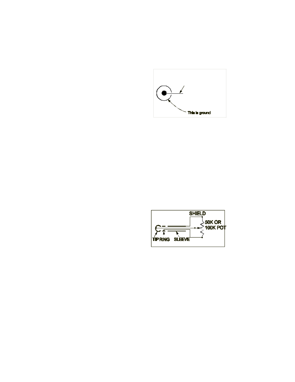
Figure 10 - Correct wiring of an
expression pedal for the MF-104SD.
This must be
+9V to +15V DC.