Moog Music MF-104Z Analog Delay User Manual
Page 10
10
jack. You should adjust the OUTPUT LEVEL after you set the DRIVE
control. Set the OUTPUT LEVEL control so that you get the desired
balance between on-line and bypass signals when you toggle the
stomp switch.
The LOOP GAIN control adjusts the signal level which is applied
to the LOOP IN jack. You use this control to set the right loop gain for
the external sound processing device that you connect between the
LOOP OUT
jack and the LOOP IN jack. Connect the external sound
processor and set the LOOP GAIN control as follows:
1. Use patch cords to connect a) the MF-104Z LOOP OUT jack to the
Audio In (instrument) jack on your processor, and b) the Audio Out
(amplifier) jack on your processor to the MF-104Z LOOP IN jack.
2. Turn the external processor on. Playing your instrument, set your
processor's Drive or Input Level control for proper operation of the
processor.
3. Set your processor's Output Level control (if it has one) to balance
your processor's bypass signal with its on-line signal.
4. Finally, set your MF-104Z's LOOP GAIN control so the LOOP
LEVEL
light is green-yellow or yellow-red most of the time that you
are playing, and flashes red only
briefly on loudness peaks.
An alternate way of setting
up the gain of the external feedback
loop is a) to temporarily connect
your external processor's output
directly to your amplifier instead of
to the MF-104Z's LOOP IN jack,
then b) perform steps 2. and 3. as
written above, c) connect your
external processor's output to the
MF-104Z’s LOOP IN jack and d)
perform step 4. This may be somewhat easier for some types of
processing devices.
Note again that the LOOP GAIN control and the LOOP LEVEL
light have no effect when the feedback mode switch is on INT.LOOP.
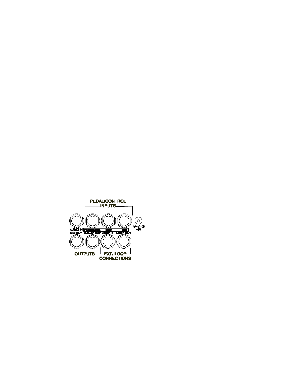
Figure 4 - The MF-104Z’s jack panel.