Moog Music MF-107 FreqBox User Manual
Page 16
16
FREQBOX FUNCTIONS
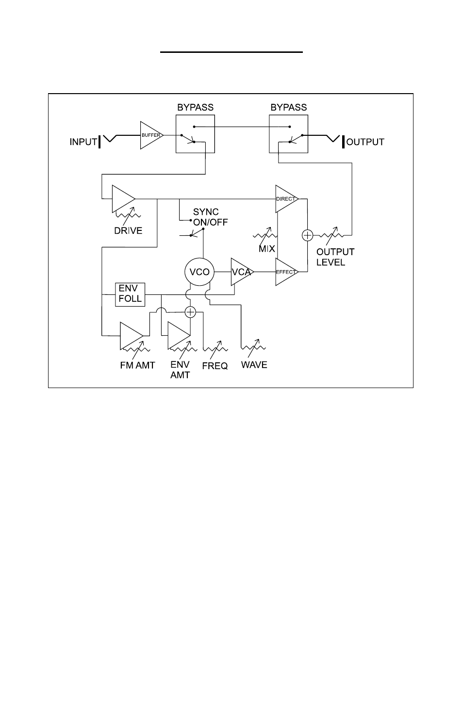
Here is a block diagram of the FreqBox signal and control path:
The input is passed through a unity gain buffer, and then connected
to the bypass circuit. In bypass, the buffered input signal is connected
directly to the output. In effect active mode, the buffered input signal is
passed to the drive circuit. The drive circuit feeds the mix direct VCA,
the envelope follower, VCA for the FM input to the VCO, and the sync
input to the VCO.
The envelope follower detects the amplitude of the drive output and
generates a CV that goes higher as the drive output gets louder. The
output of the envelope follower is applied to the control input of the VCA
controlling the loudness of the VCO signal, and the input of the VCA
for the envelope follower that modulates the VCO frequency. The VCO
is a signal source. Its waveform is determined by the Waveform control.
The frequency is determined by the Frequency control, the Envelope
Follower VCA, and the FM Amount VCA. The VCO signal passes to
a VCA with an output controlled by the envelope follower CV so that
the amplitude of the VCO signal will follow the amplitude of the direct
signal.
Figure 14-Block Diagram of the FreqBox