General performance information – Nemco Electronics Performance Info User Manual
Page 7
General Performance Information
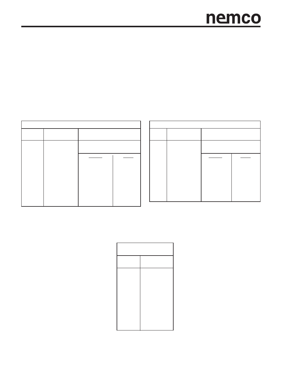
Surface Mount Tantalums
Dipped Radial
Case
Case
Temperature Derating Factors
Temperature Derating Factors
Size
for power dissipation by case size
Size
for power dissipation by case size
A
0.075
A
0.045
B
0.085
B
0.050
C
0.110
C
0.055
D
0.150
Temp °C
Factor
D
0.060
Temp °C
Factor
H
0.165
E
0.065
Z
0.250
+25
1.00
F
0.075
+25
1.00
+85
0.80
G
0.080
+85
0.40
XL
0.055
+125
0.16
H
0.085
+125
0.09
AL
0.065
J
0.090
BL
0.080
K
0.100
CL
0.090
L
0.110
DL
0.125
M
0.120
N
0.130
P
0.015
O
0.140
R
0.025
Do not use these derating factors when calculating
ripple current ratings. Use temperature correction
factors.
Do not use these derating factors when calculating
ripple current ratings. Use temperature correction
factors.
Free Air
Max Power
Dissipation (W)
Free Air
Max Power
Dissipation (W)
Power Dissipation
The maximum power dissipation at 25°C has been calculated for the various ranges, and are shown (see Table) together with
temperature derating factors up to 125°C. For leaded components the values are calculated for parts supported in air by their
leads (free space dissipation). For surface mount components, the free air values can be approached by correct thermal man-
agement of the board. Operation in confined spaces with no heat sinking may lead to a tenfold reduction in the dissipation
required to heat the capacitors to 10°C above their ambient. The ripple ratings are set by defining the maximum temperature
rise allowable under worst case conditions, i.e. with resistive losses at their maximum limit. This differential is normally at 10°C
at room temperature dropping to 2°C at 125°C. In application (this is particularly critical for surface mount components) cir-
cuit layout, thermal management, available ventilation and signal waveform may significantly affect the values. It is recom-
mended that temperature differential between the device and the ambient temperature is less than 10°C up to 85°C and less
than 2°C between 85°C and 125°C. Derating factors for temperatures above 25°C are also shown. The maximum permissi-
ble power dissipation should be multiplied by the appropriate derating factor. For certain applications, e.g. power supply filter-
ing, it may be desirable to obtain a Low ESR device to enable higher ripple currents to be handled. Please contact our tech-
nical sales office for discussion.
•
Self Inductance Value (ESL) for surface mount devices
The self inductance value can be important for resonance frequency evaluation.
This table shows typical ESL values per case size.
Self Inductance Value
(ESL)
Case
Size
A
1.8
B
1.8
C
2.2
D
2.4
H
2.5
Z
2.4
XL
1.4
AL
1.8
BL
1.8
CL
2.2
DL
2.4
P
1.1
R
1.2
Typical
Self Inductance
Value (nH)
•