Nemco Electronics Performance Info User Manual
Page 3
General Performance Information
z Reverse voltage A small degree of reverse voltage is permissible for short periods. Limiting reverse voltage excursion to
the maximum limits shown will avoid a reduction in the components life expectancy. The maximum allowable reverse
voltage is summarized as follows:
The values quoted are not intended to cover continuous reverse operation.
They are designed to cover exceptional conditions of small levels into reverse polarity.
Non-Polar operation
If higher reverse voltages are unavoidable, then two capacitors, each of twice the required
capacitance and of equal tolerance and rated voltage, should be connected in a back-to-back configuration, i.e. both cathodes
joined together.
z DC Leakage Current The DC leakage current is the current that, after a three to five minute charging period, flows through
a capacitor when voltage is applied. It is dependent upon the voltage applied, the time the voltage was applied and th ecom-
ponent temperature. The leakage current increases with increasing temperature. The leakage current decreases when
reduced voltages are applied. The DC leakage current is measured at +25°C with rated voltage applied, through a 1000 ohm
resistor connected in series in the measuring circuit. Reforming of solid tantalum capacitors is unnecessary even after pro-
longed periods without the application of voltage.
@
25°C the DCL values are shown in part number tables
@
85°C the DCL should not exceed 10 times the value
@ 125°C the DCL should not exceed 12 times the value
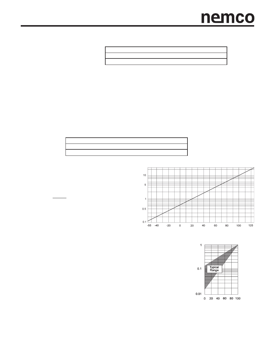
Temperature Dependance of the Leakage Current
For operation between +85°C and +125°C, the
maximum working voltage must be derated and
can be found from the following formula.
V max =
1 - (T - 85)
x V
R
volts
120
T is the required operating temperature.
Temperature (°C)
Voltage Dependence of the Leakage Current The leakage current drops
rapidly when reduced voltages are applied. The effect of voltage derating on
leakage current gives a significant increase in reliability for any application.
Rated Voltage U
R
%
Leakage Current Ratio I/I
R25
Leakage Current Ratio I/IV
R
(
)
25°C
10% of rated voltage not exceeding 1.0 volt
85°C
3% of rated voltage not exceeding 0.5 volt
125°C
1% of rated voltage not exceeding 0.1 volt