Banks Power Ford Trucks: (Diesel ’03 - 07 6.0L Power Stroke) Tuner- Six-Gun Diesel Tuner w_Optional Banks Brake & Speed-Loader '03-07 For use with Six-Gun_EconoMind Selector Switch User Manual
Page 30
30
96808 v.14 .0
If not installing optional
thermocouple, skip to Section 5.
1.
The thermocouple monitors
the temperature of the exhaust
gases entering the turbocharger
at the turbine housing. Installation
requires that the exhaust manifold
be drilled near the manifold outlet.
It is recommended that the manifold
be removed from the engine to
thoroughly clean out all metal chips
from drilling. All metal shavings must
be cleaned from the manifold to avoid
turbine wheel damage and possible
interference with the turbocharger’s
variable geometry turbine stage.
2.
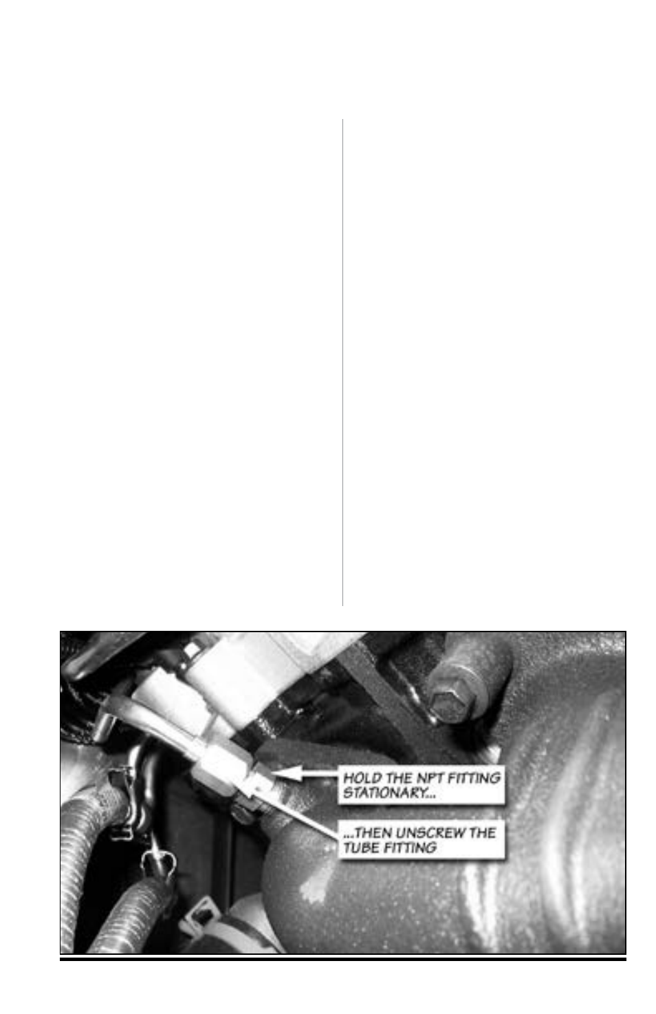
Disconnect the Exhaust Back
Pressure Sensor tap located at the
front of the driver side manifold. The
pressure tap must be removed by
using a
9
⁄
16
” open-end wrench to hold
the fitting stationary, and loosen the
tube using a
5
⁄
8
” open-end wrench.
The fitting is shown in Figure 30.
NoTE: Failure to hold the fitting
stationary will damage the tube upon
removal.
3.
Remove the driver side exhaust
manifold.
4.
Drill a
7
⁄
16
” hole in the driver side
exhaust manifold at the location
shown in Figure 31.
5.
Tap the hole for a
1
⁄
4
” NPT thread.
check the thread depth as you tap
by periodically removing the tap and
screwing the pipe coupling into the
tapped hole. The coupling should
thread in 3 to 3
1
⁄
2
turns hand tight. Do
not install the probe in place at this
time. Caution: Running the tap
too deeply can prevent the pipe
fitting from properly sealing.
6.
Remove the NPT fitting from the
thermocouple and install it on the
exhaust manifold. Use anti-seize
lubricant on the threads and torque to
14–16 lb-ft.
7.
Remove all metal chips from
the exhaust manifold. Note: Failure
to remove all metal chips could
result in catastrophic damage to
the turbocharger’s turbine wheel or
interfere with the operation of the
variable geometry vane mechanism.
8.
Re-install the exhaust manifold.
Apply anti-seize lubricant to the
manifold bolt threads and torque to
28 lb-ft. Use the tightening sequence
shown in Figure 32.
Section 4
OPTIONAL THERMOCOUPLE INSTALLATION
Figure 30: Location of the static exhaust pressure line tap