Banks Power Cummins Motorhomes: (Diesel ’93 - 98 B5.9L & C8.3L) PowerPack & Stinger systems w_Twin Ram Manifold 5.9L, 190-210-230-hp rated User Manual
Page 8
GAUGE LIGHTING
connect the 4-pin connector of each gauge
into the back of its corresponding gauge.
A. crimp the remaining black and red wires
from each 4-pin connector gauge harness to the
butt connectors as shown in Figure 4.
B. strip one end of the reD wire and crimp it to
the butt connector containing the reD wires from
step ‘a’.
C. strip one end of the black wire and crimp it
to the butt connector containing the black wires
from step ‘a’.
D. route the red wire to the fuse box. locate
the appropriate fuse for instrument lighting in the
owner’s manual. cut the red wire as required
and strip the end. crimp the push on connector
to the reD wire and connect to the fuse as shown
in Figure 4. alternatively, locate power wire to
dimmer switch and install T-tap. cut the red wire
as required and strip the end. crimp the push on
T-tap connector to the reD wire and connect to
T-tap on dimmer power wire.
E. locate a metal surface that will serve as an
acceptable chassis ground. cut the black wire to
a sufficient length that will allow it to reach the
chassis ground and strip the end crimp the ring
terminal to the black wire ash shown in Figure 4.
F. Drill a 1/8” hole, if required, to attach the ring
terminal to the chassis ground.
Caution: If drilling, check the backside to
make sure there are no components that may
be damaged by drilling.
G. use the supplied self-tapping screw to secure
the ring terminal to the chassis ground.
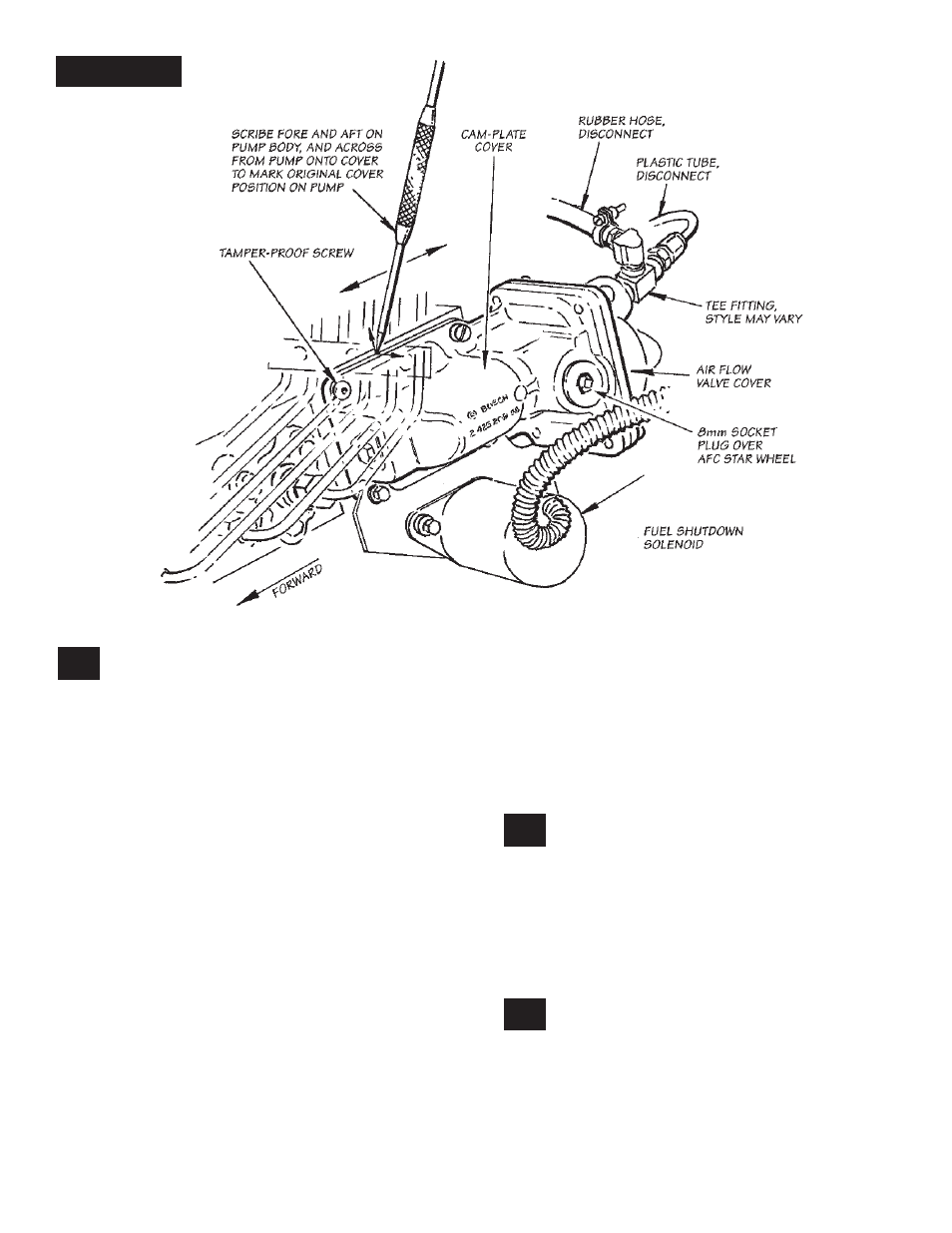
OTTOMIND INSTALLATION
To realize power gains made available by
the increased airflow through the banks
components, the fuel delivery of the injection
pump must also be increased. This procedure
will provide the additional fuel flow required.The
injection pump is located on the upper left side of
the engine, and can be identified by the row of six
injector pressure tube connections on top of the
pump body.
loosen the upper hose clamp on the boost
tube hose joint at the intake manifold
inlet casting. remove the hose from the inlet
casting and push out of the way. cover the intake
manifold opening and the open end of the boost
tube with clean rags to prevent foreign object
entry.
34.
35.
33.
p.n. 96385
8
Figure 5