Banks Power Cummins Motorhomes: (Diesel ’93 - 98 B5.9L & C8.3L) PowerPack & Stinger systems w_Twin Ram Manifold 5.9L, 190-210-230-hp rated User Manual
Page 12
engaged on the manifold adapter and the clamp is
positioned properly on the hose, then tighten the
clamp nut.
For Stinger installation, proceed to CHECkING
ENGINE PERFORMANCE.
TWINRAM MANIFOLD INSTALLATION
loosen the tube nuts at both ends of all
six fuel injection lines. remove the two
bolts from the intake manifold cover that retain
the fuel injection line clamp brackets. remove
the injection lines as an assembly. it is very
important that no dirt or debris be introduced
to the fuel system while the injector lines are
removed. place the plastic caps provided over
each injector nozzle and each fitting on the
injection pump. set the injector lines aside in
a clean place. remove the remaining manifold
cover bolts and remove the remaining manifold
cover bolts and remove the manifold cover. Make
note of various bolt lengths and their locations.
cover the cavity in the cylinder head with clean
rags to keep foreign material out while working.
clean any remaining gasket residue from the
cast iron surface of the cylinder head. Take
care to keep the gasket material from entering the
cylinder head cavity. remove any rags placed in the
head cavity at this time to allow for the installation
of the Twinram manifold components.
if your motorhome is equipped with an air
compressor, the inlet air for the compressor
may be drawn from the intake manifold. a fitting
and a length of hose are provided for adaptation
to accomodate the compressor feed. install the
air compressor feed fitting in the large threaded
hole in the Twinram base plate. if your engine
does not take air from the intake manifold, install
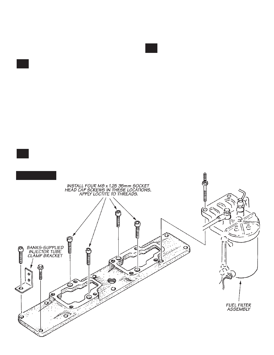
the pipe plug provided in the threaded hole. place
the new gasket provided over the bolt pattern
in the cylinder head and place the base plate in
position. apply a drop of loctite to the threads
of four metric socket-head capscrews provided
and install into the recessed holes in the base
plate. see Figure 9
.
install ten factory fasteners
finger tight in the remaining positions. note the
location of two slightly longer factory fasteners
for mounting the fuel filter bracket. also note the
location of the new injection line bracket provided.
51.
52.
53.
Figure 9
12
p.n. 96385